Cutlery dispenser

a dispenser and plastic technology, applied in the direction of racks, flat article dispensing, packaging, etc., can solve the problem of high price of carts

Active Publication Date: 2018-08-21
SMITH PATRICK J
View PDF30 Cites 16 Cited by
  • Summary
  • Abstract
  • Description
  • Claims
  • Application Information

AI Technical Summary

Problems solved by technology

In dispensers such as U.S. Pat. No. 8,210,364, the cutlery must be reloaded from the top of the housing, which is problematic, especially if the cutlery dispenser is mounted to a wall above eye level.
The problem with traditional cartridge dispensers, such as the dispenser taught in U.S. Pat. No. 6,336,568 to Tucker, is that the cartridges are expensive.

Method used


Image

  • Cutlery dispenser
  • Cutlery dispenser
  • Cutlery dispenser

Examples


Embodiment Construction

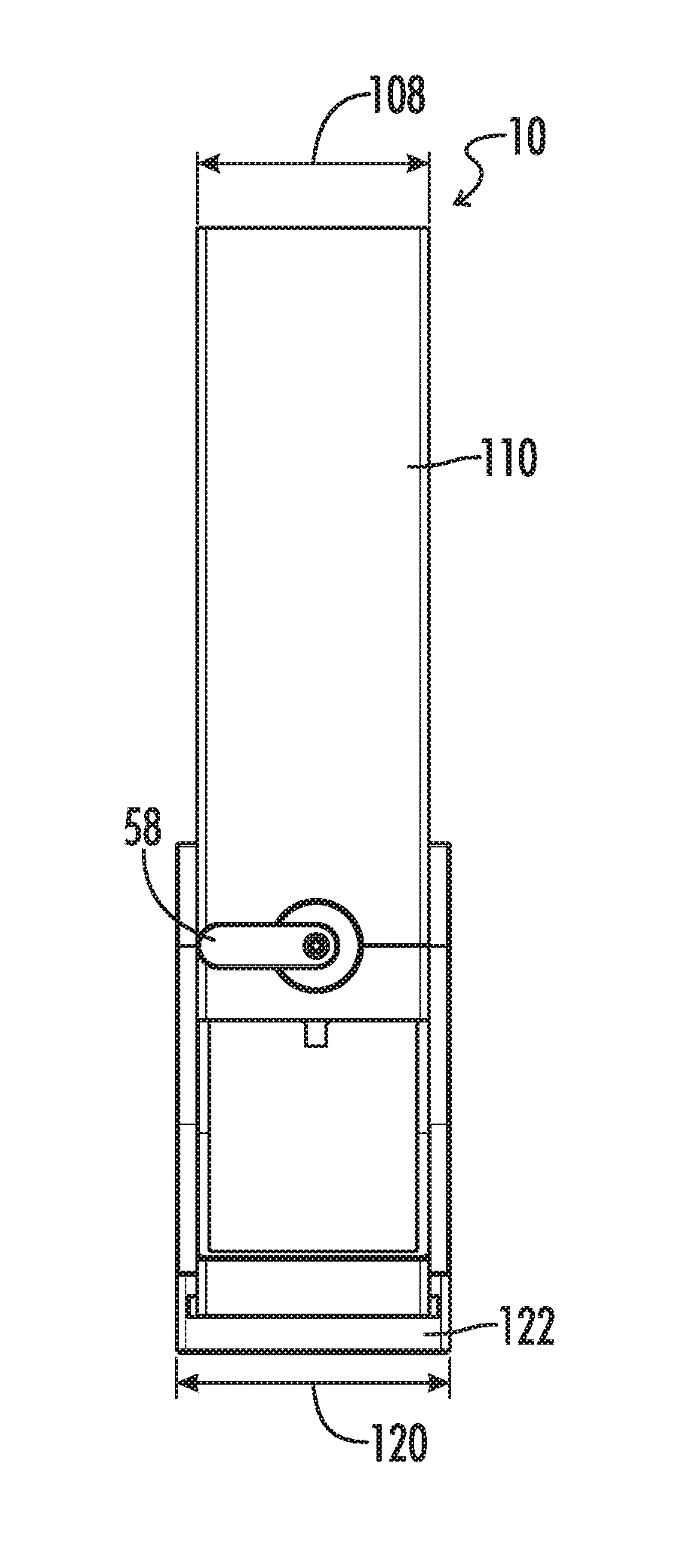
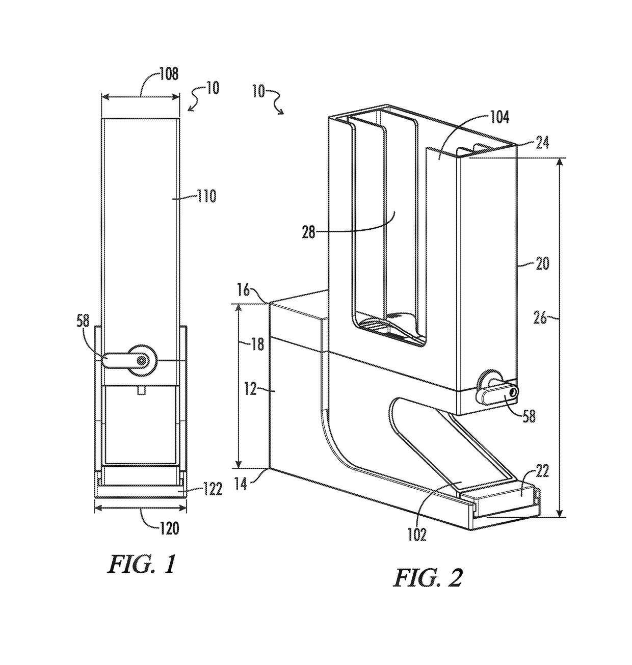
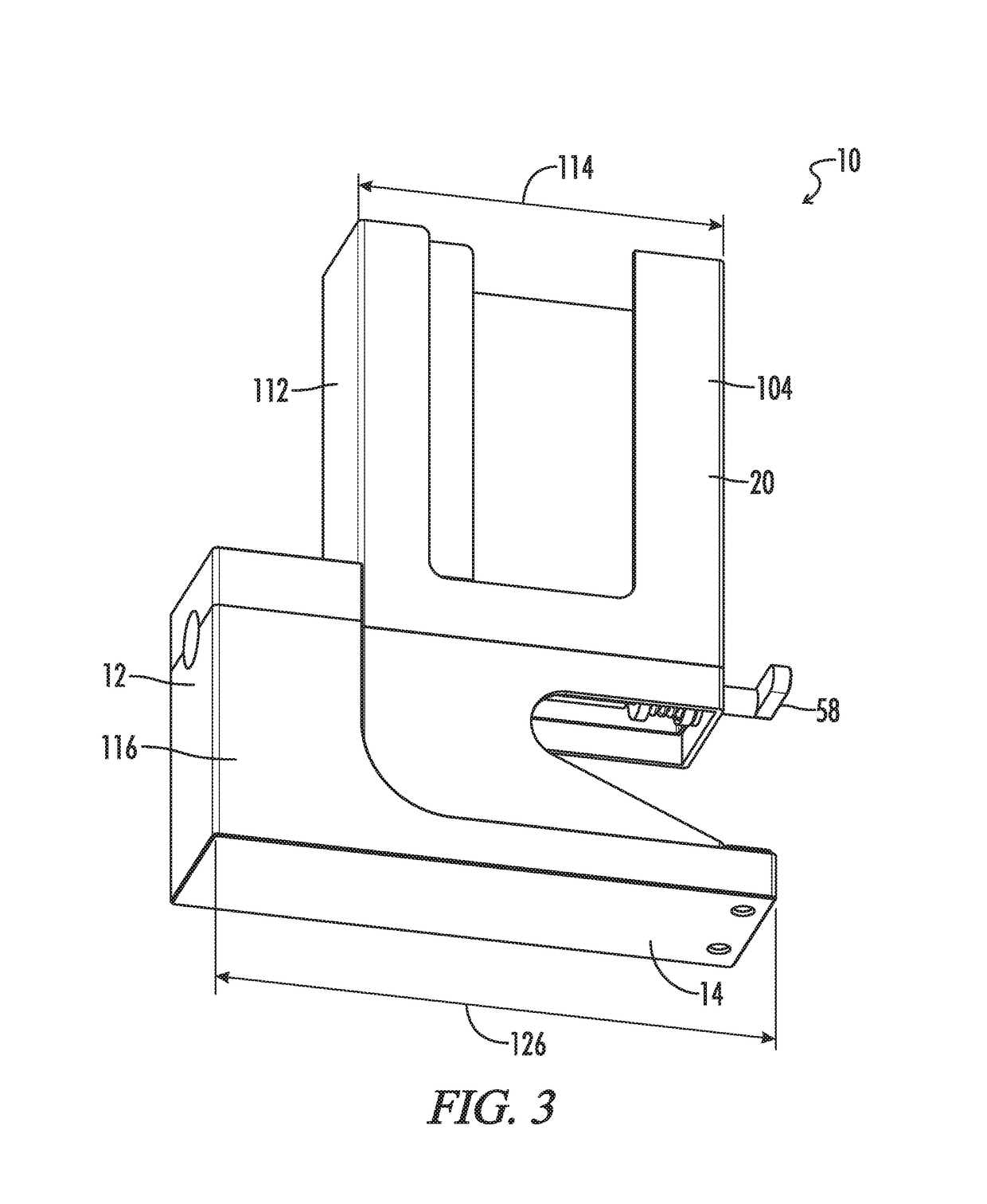
[0036]Referring to FIGS. 1-22, the present disclosure provides a cutlery dispenser generally designated by the numeral 10. In the drawings, not all reference numbers are included in each drawing for the sake of clarity. It will also be understood that FIGS. 1-22 are CAD drawings, drawn to scale. However, other dimensions are possible.

[0037]Referring to FIGS. 1-22, the present disclosure provides a cutlery dispenser 10 comprising a base 12 comprising a base bottom 14 configured to rest on a surface (e.g., on the ground or on a countertop), a base top 16 opposite the base bottom 14, and a base height 18 extending from the base bottom 14 to the base top 16. The cutlery dispenser 10 further comprises a cartridge 20 attached to the base 12 and comprising a cartridge bottom 22, a cartridge top 24, a cartridge height 26 extending from the cartridge bottom 22 to the cartridge top 24, and a chamber 28 located in the interior of the cartridge 20. The cutlery dispenser 10 further includes a st...


PUM


Abstract

A plastic cutlery dispenser having a base and a cartridge is described. The cartridge may be slideable relative to the base. In some embodiments, the base has a base dispensing mechanism and the cartridge has a cartridge dispensing mechanism configured to mate with the base dispensing mechanism. In some embodiments, when the base and cartridge dispensing mechanisms mate, the cutlery dispenser is configured to dispense cutlery located within the cartridge one piece of cutlery at a time.

Description

RELATED APPLICATIONS[0001]This patent application is a continuation of International Patent Application No. PCT / US2017 / 040466, filed Jun. 30, 2017 and entitled “CUTLERY DISPENSER”, which claims priority under 35 USC 119 to U.S. Application Ser. No. 62 / 357,034 entitled CUTLERY DISPENSER, filed Jun. 30, 2016, the contents of both of which are incorporated herein by reference in their entirety.TECHNICAL FIELD[0002]The present disclosure relates to plastic cutlery dispensers.BACKGROUND OF THE INVENTION[0003]Dispensers of plastic cutlery pieces (e.g., knives, spoons, forks and sporks) are well known in the art. U.S. Pat. No. 6,336,568 to Tucker, the entire contents of which are incorporated herein by reference, relates to a cartridge-type dispenser that dispenses cutlery pieces one at a time upon hand operation of an externally accessible utensil delivery controller. The dispenser includes a housing having at least one interior compartment in communication with an exit opening. At least ...

Claims


Application Information

Patent Timeline
Patent Type & Authority Patents(United States)
IPC IPC(8): A47F1/10B65D83/08B65D83/22
CPCA47F1/10B65D83/0858B65D83/222B65D83/0876B65D2583/005A47F2001/103
Inventor SMITH, PATRICK J.
Owner SMITH PATRICK J
Why Eureka
Try Eureka