
Cutlery support

a technology for supporting and cuttinglery, which is applied in the direction of stand/trestle, tableware, show hangers, etc., can solve the problems of difficult to solve, difficult to clean, and microbial build-up in the holder, so as to promote the retrieval and return of cutlery, easy to clean, and easy to clean

Inactive Publication Date: 2010-09-28
RUAN YING GANG
View PDF27 Cites 10 Cited by
  • Summary
  • Abstract
  • Description
  • Claims
  • Application Information

AI Technical Summary

Benefits of technology

[0006]The present invention overcomes these problems by providing a cutlery support which provides for a large open area where the knife blades are retained but with minimal contact between the knife blades and the cutlery support. The knife holder is designed to provide ease of use in order to promote the retrieval and return of the cutlery by kitchen staff, as opposed to resting the knives even temporarily on the surface. Moreover, the cutlery support hereof is easy to clean, and in preferred embodiments, aids the user in seeing any food or other contaminant build up on the support. In addition, the cutlery support hereof aids in maintaining separation of the blades of adjacent knives, with the additional benefit of providing for magnetic retention of ferromagnetic blades where temporary support is desired by the user. Beneficially, the cutlery support hereof is easy to clean, while permitting visual observation of the blades of the knives held therein, and protects the supported cutlery from dislodgment.
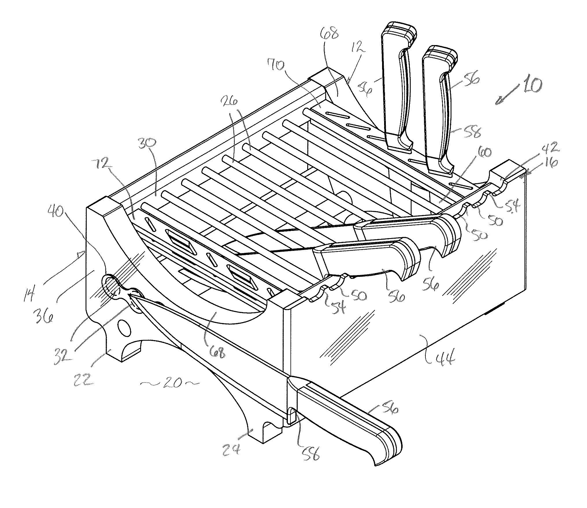
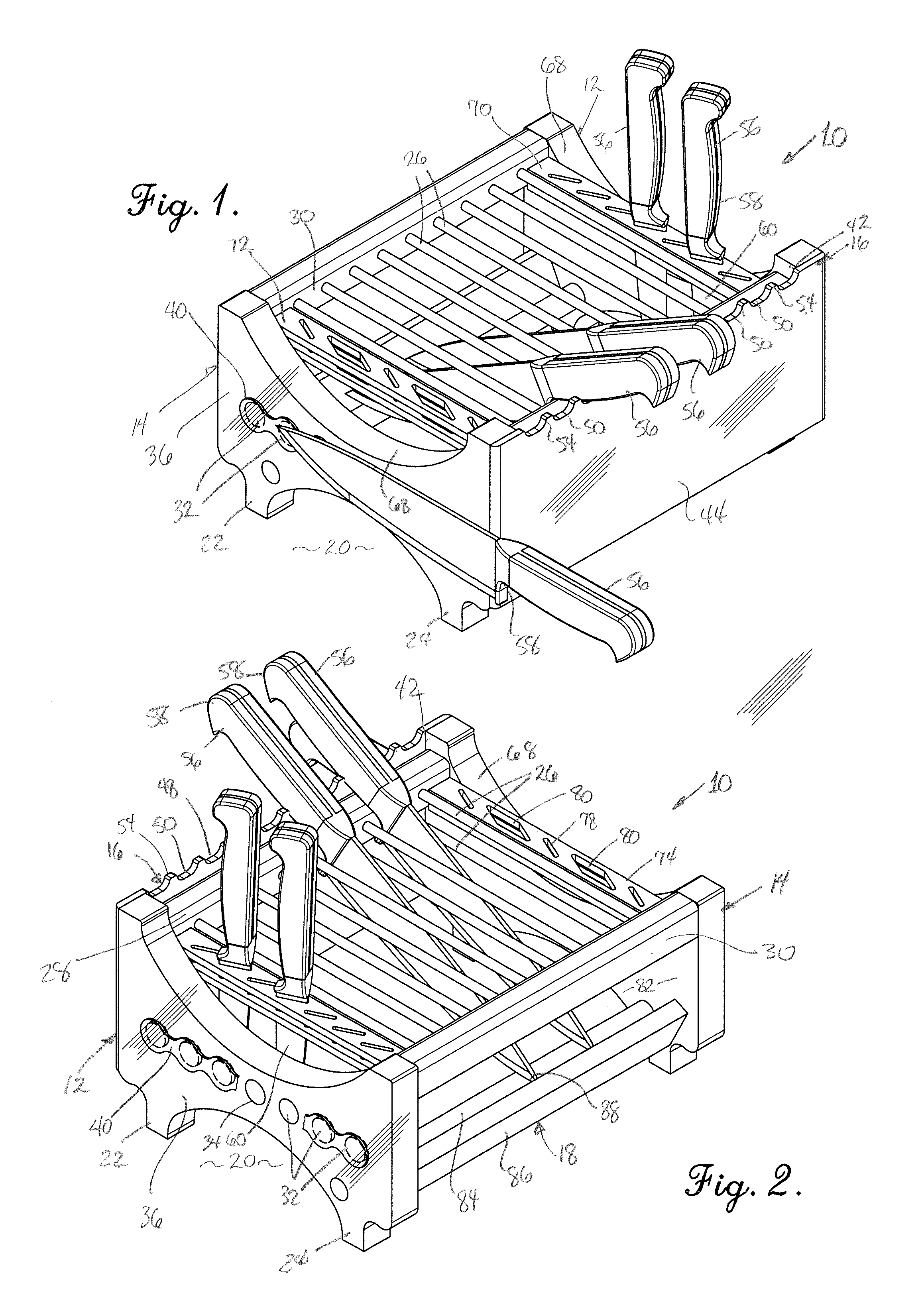
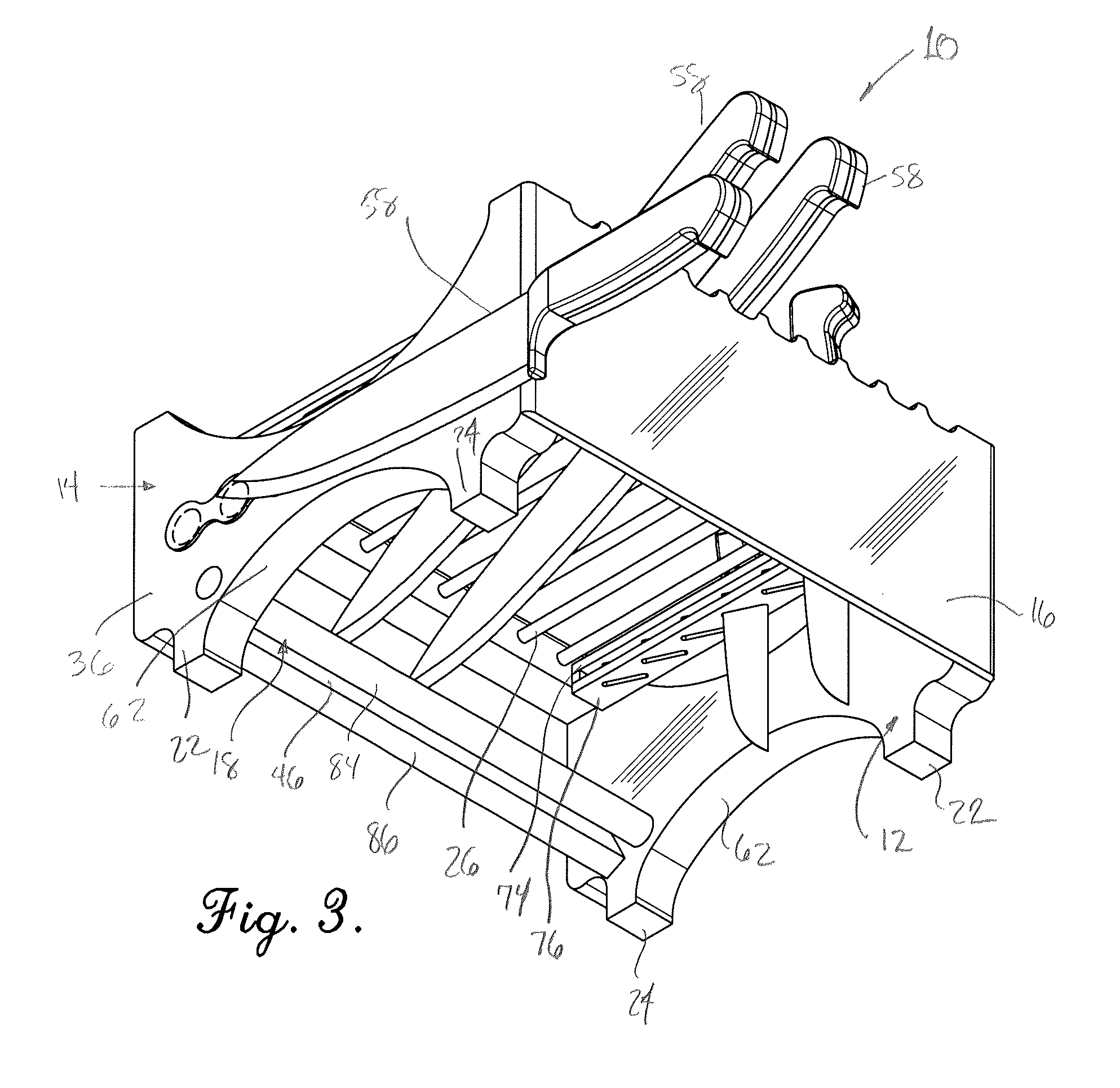
[0007]Broadly speaking, the cutlery support of the present invention includes first and second spaced-apart upright standards, a handle support and a blade support which extend between and are supported by the standards above the supporting surface, with an open area generally interior to the standards, handle support and blade support. The blade support is configured to provide minimal contact, preferably only a single point or two points of contact with knife blades having their handles resting upon the handle support. The blade support may also include a blade stopper positioned adjacent a cutting edge support where the length of a knife would otherwise cause the knife to slide over the cutting edge support. In this way, the knife blade has a minimal amount of contact with the cutlery support to thereby avoid transferring any food particles from the blade to the cutlery support. Further, the large open area facilitates cleaning of the cutlery support.
[0008]The preferred embodiment of the cutlery support provides additional advantageous features. A plurality of separators extending generally parallel to the upright standards. The separators are readily cleaned, but may be useful in maintaining spaced separation between the blades of adjacent knives. In addition, one or a plurality of transverse supports be provided adjacent, and most preferably parallel to, the separators, whereby small knives such as paring knives or kitchen shears may be supported with their handles extending in a generally vertical orientation and maintained above the transverse supports which permit the blades, but not the handles, of such cutlery, to pass therethrough. In particularly preferred embodiments, the upright standards are provided with one or a plurality of magnetic bodies embedded within one or both of the standards. The magnetic bodies help to retain blades of ferromagnetic material of knives above a surface when the user wishes to temporarily “park” a knife without placing it inside the cutlery support. In addition, the cutlery support may be constructed of a transparent material which facilitates the ability of the user to see both the particular knife blade desired as well as any food particles left on the support which needs to be removed and cleaned.

Problems solved by technology

Often, kitchen workers are confronted with problems as to how to store knives when not in use, even for a few moments.
This can result in transfer of contamination from one-knife to another and microbial build-up in the holder, which is often difficult to resolve.
In addition, inspection authorities may issue citations where commercial kitchens fail to adhere to cleanliness standards.

Method used


Image

  • Cutlery support
  • Cutlery support
  • Cutlery support

Examples


Embodiment Construction

[0017]Referring now to the drawing, a cutlery support 10 in accordance with the present invention broadly includes first and second upright standards 12 and 14, a handle support 16 and a blade support 18. The handle support 16 and the blade support 18 are mounted, by adhesive, heat or chemical welding, or by fasteners to the upright standards 12 and 14 whereby they are spaced from and above a supporting surface 20 on which the legs 22 and 24 of each of the standards rest. A plurality of elongated separators 26 are provided to extend substantially perpendicular to the handle support and blade support and parallel to the upright standards 12 and 14. First and second transverse supports 28 and 30 are mounted to extend substantially perpendicular to upright standards 12 and 14. At least one, or preferably both of the upright standards 12 and 14 have embedded magnetic bodies 32 therein.

[0018]In greater detail, the upright standards are configured to extend upwardly from a supporting surf...


PUM


Abstract

A cutlery support includes first and second upright standards, a blade support, a handle support, and a plurality of separators defining an open area therebetween. Cutlery such as knives are placed on the cutlery support to engage the blade support and the handle support with the blade lying within the open area. The blade support is preferably configured with a blade stopper and cutting edge support, each of which engage the blade at only one point. Smaller pieces of cutlery, such as shears and small knives, may be carried by a cutlery receiver with their blades in an upright orientation lying within the open area. Additional knives having ferromagnetic blades may be held for temporary use by magnets in the upright standards. The standards, blade support, handle support and separators are preferably of a non-porous, transparent and corrosion-resistant material.

Description

BACKGROUND OF THE INVENTION[0001]1. Field of the Invention[0002]The present invention concerns a support for cutlery such as knives, kitchen shears, cleavers, sharpening steels and like utensils which supports the cutlery above a supporting surface with minimum contact and to promote cleanliness of the support. In addition, in preferred embodiments, the cutlery support hereof is intended to provide for air circulation to dry the blades of the cutlery after rinsing or cleaning, to keep the blades separated when carried on the support, to provide an ability to magnetically retain a blade of a knife for quick access, and to more readily view the cutlery during storage on the support.[0003]2. Description of the Prior Art[0004]In both home and commercial kitchens, knives are used during food preparation and it is important, if not essential, that the knives be kept clean to avoid contamination of other foods. This is for both reasons of health and taste.[0005]Often, kitchen workers are c...

Claims


Application Information

Patent Timeline
IPC IPC(8): A47F7/00
CPCA47G21/14A47J47/16
Inventor RUAN, YING GANG
Owner RUAN YING GANG
Learn More