
Casting die device and casting method

a casting die and casting method technology, applied in the field of casting die devices and casting methods, can solve the problems of difficult to reduce casting defects in the inner hole formed by the core pin, and achieve the effects of simple structure, good appearance and not easy to reduce casting defects

Active Publication Date: 2018-08-28
HITACHI ASTEMO LTD
View PDF8 Cites 1 Cited by
  • Summary
  • Abstract
  • Description
  • Claims
  • Application Information

AI Technical Summary

Benefits of technology

The patent describes a method to reduce casting defects on the inner surface of a valve hole, which is difficult to reach with traditional methods. The method involves applying vibrations to the pressurizing pin, which can be difficult to achieve because the pressurizing pin does not make direct contact with the inner hole surface. The patent also introduces a hollow displacement drive source that makes it easy to apply vibrations to the pressurizing pin. The technical effect of this method is the reduction of casting defects on the inner surface of valve holes.

Problems solved by technology

However, in this method, it is difficult to reduce casting defects in the inner hole formed by the core pin, such as the valve hole.

Method used


Image

  • Casting die device and casting method
  • Casting die device and casting method
  • Casting die device and casting method

Examples


Embodiment Construction

[0027]Hereinafter, a preferred embodiment of a casting method according to the present invention will be described in detail in connection with a casting die device for carrying out the casting method, with reference to the accompanying drawings. In the embodiment of the present invention, a valve body of a spool valve is shown as an example of a cast product.

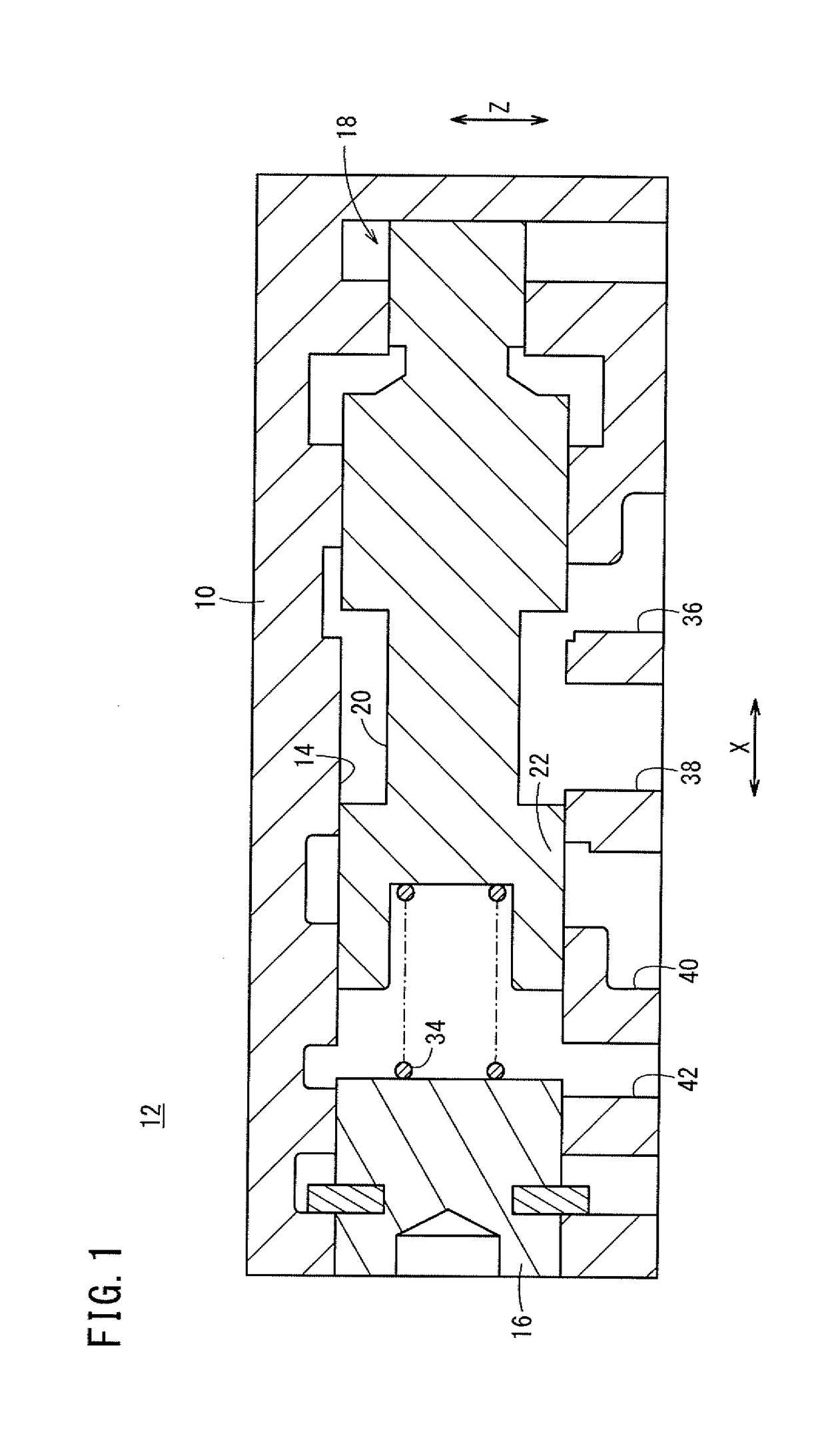
[0028]Firstly, the spool valve will be described with reference to FIG. 1. FIG. 1 is a vertical cross-sectional view taken along a thickness direction (the direction indicated by arrow Z in FIG. 1) of a spool valve 12. The spool valve 12 has a valve body 10 as a cast product. In the valve body 10, a valve hole 14 is formed as an inner hole extending in an axial direction, e.g., in a longitudinal direction (the direction indicated by arrow X in FIG. 1).

[0029]The valve hole 14 opens on one end in the direction of the arrow X. The opened end is closed by a cap member 16. The other end is closed by an inner wall of the valve body 1...


PUM

PropertyMeasurementUnit
vibration frequencyaaaaaaaaaa
depthaaaaaaaaaa
pressureaaaaaaaaaa

Abstract

A casting die device and a casting method. The casting die device has a core pin for forming an inner hole in a casted article. The core pin is a hollow body, and a pressurizing pin is inserted into a hollow inner part of the core pin. Vibrations from a vibrator of a micro vibration machine are imparted to the pressurizing pin via a vibration transmission member. The vibrations further propagate to the core pin from the pressurizing pin, and then propagate to the area surrounding the core pin in a molten metal that has been poured into a cavity.

Description

TECHNICAL FIELD[0001]The present invention relates to a casting die device and a casting method for obtaining a cast product in which an inner hole, at least one end of which is open, is formed.BACKGROUND ART[0002]High pressure casting (die casting) is known as a method of obtaining, e.g., cast products of aluminum alloy. In the high pressure casting, the obtained cast products have excellent dimensional accuracy, and the high pressure casting enables mass production advantageously. Therefore, the high pressure casting method has been adopted widely.[0003]In high pressure casting, molten metal poured into a plunger sleeve is extruded by a plunger tip, and the molten metal is supplied to a cavity. That is, an injection process is performed in the casting method.[0004]In the process, the molten metal passes through a narrow runner and a gate, and is supplied into a cavity. In this case, for example, the molten metal staying in the gate may be solidified earlier than the molten metal w...

Claims


Application Information

Patent Timeline
Patent Type & Authority Patents(United States)
IPC IPC(8): B22D17/20B22D17/22B22D27/08B22D17/24B22D25/02
CPCB22D17/2069B22D17/22B22D27/08B22D25/02B22D17/24
Inventor UEHARA, TETSUYASAKUMA, FUMIHIRO
Owner HITACHI ASTEMO LTD
Learn More