Thermoelectric device

a thermoelectric device and thermoelectric element technology, applied in the direction of engines, mechanical equipment, machines/engines, etc., can solve the problems of less efficient implementation, negative influence on the overall efficiency of the vehicle, connection of thermoelectric elements to fluid-conveying thermoelectric devices, etc., to achieve the lowest possible thermal resistance, simple integration of the thermoelectric device, and not sensitive

Inactive Publication Date: 2018-09-11
MAHLE INT GMBH
View PDF50 Cites 0 Cited by
  • Summary
  • Abstract
  • Description
  • Claims
  • Application Information

AI Technical Summary

Benefits of technology

[0013]It is therefore an object of the present invention to provide a thermoelectric device that produces a lowest possible thermal resistance between the fluids and the thermoelectric elements and is also not sensitive to thermal stresses and enables simple integratability of the thermoelectric device into a heat exchanger. In addition, an arrangement is provided of a single or plurality of thermoelectric devices in a heat exchanger.

Problems solved by technology

This has a negative influence on the overall efficiency of the vehicle.
The publications EP 1230475 B1 (which corresponds to U.S. Pat. No. 6,474,060), EP 1475532 A2 (which corresponds to U.S. Pat. No. 7,100,369), WO 2007026432, JP 10281015AA, JP 2000282960AA, JP 2004068608AA, JP 2005083251AA, or JP 2005117836AA disclose approaches by using such a thermoelectric device; however, these implementations are less efficient because of the disadvantageous connection of the thermoelectric elements to a heat exchanger.
At present particularly disadvantageous in the prior art is the connection of the thermoelectric elements to the fluid-conveying thermoelectric devices, particularly with respect to a lowest possible thermal resistance between the fluids and the thermoelectrically active materials.
Disadvantageous in addition is the resistance to thermal stresses in the connecting material or the thermoelectric modules.
Furthermore, the integratability of the thermoelectric modules in a device has not been optimally resolved thus far.

Method used


Image

  • Thermoelectric device
  • Thermoelectric device
  • Thermoelectric device

Examples


Embodiment Construction

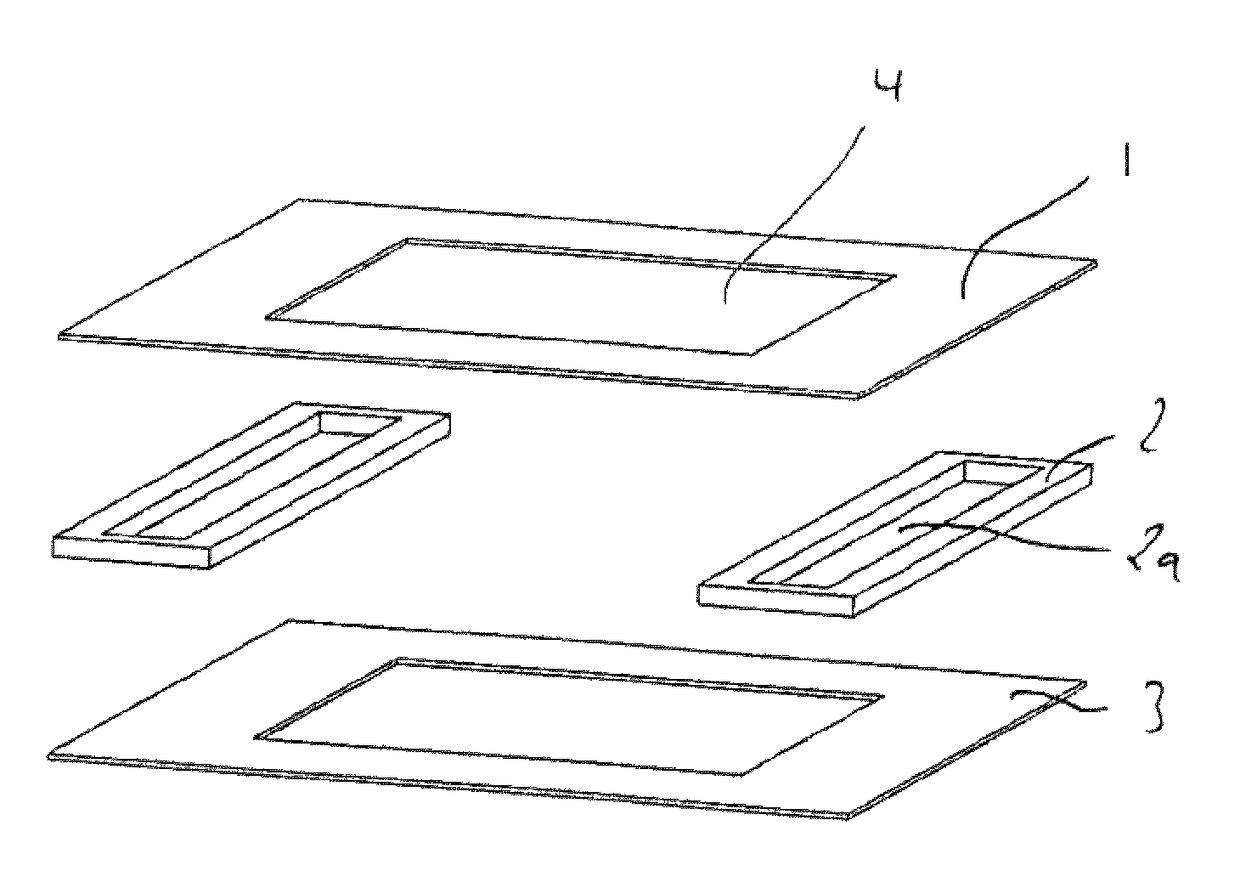
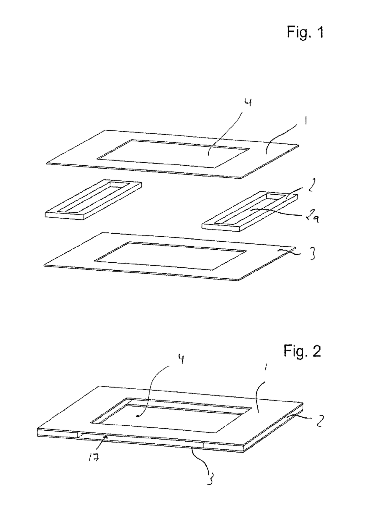
[0071]FIG. 1 shows a perspective exploded illustration of a flat tube constructed in a stacked configuration. The flat tube has substantially two walls 1, 3, which are opposite to one another. A thermal decoupling element 2 each is arranged laterally between walls 1, 3. The two walls 1, 3 have a cutout 4 in their central area.

[0072]Decoupling element 2 in its middle area has a hollow space 2a. In the assembled state of the flat tube, a gap is formed between top wall 1 and bottom wall 3 by thermal decoupling element 2. Hollow space 2a of the thermal decoupling element is covered by both walls 1, 3.

[0073]FIG. 2 shows the components shown in FIG. 1 in the assembled state. It can be seen here that a flow channel 17 forms that runs through the flat tube between walls 1, 3, which are spaced apart by thermal decoupling element 2. Flow channel 17 is opened upward or downward out of the flat tube by cutout 4 of wall 1, 3.

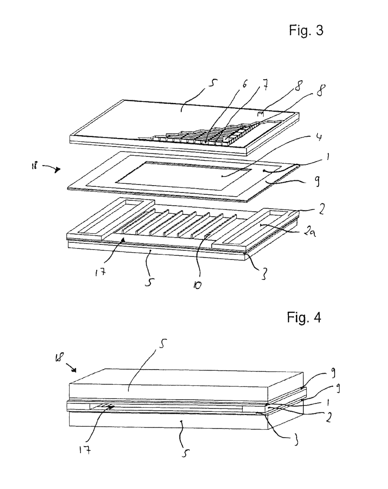
[0074]The connection of walls 1, 3 with thermal decoupling element 2 is...


PUM


Abstract

A thermoelectric device is provided that includes a duct through which a first fluid can flow. The duct has first walls and side walls which connect the first walls. At least one first wall is in thermal contact with a thermoelectric module which has a housing with at least two opposite second walls. A plurality of thermoelectric elements is arranged between the second walls. The thermoelectric elements have opposite surfaces, each of which is in thermal contact with one of the second walls of the housing of the thermoelectric module.

Description

[0001]This nonprovisional application is a continuation of International Application No. PCT / EP2013 / 066973, which was filed on Aug. 14, 2013 and which claims priority to German Patent Application No. 10 2012 214 701.2, which was filed in Germany on Aug. 17, 2012 and which are both herein incorporated by reference.BACKGROUND OF THE INVENTION[0002]Field of the Invention[0003]The present invention relates to a thermoelectric device having a flow channel, through which a first fluid can flow, whereby the flow channel has first walls and side walls connecting the first walls, whereby at least one first wall is in thermal contact with a thermoelectric module. In addition, the invention relates to an arrangement of a thermoelectric device in a heat exchanger.[0004]Description of the Background Art[0005]In motor vehicles a major part of the energy stored in fuel is converted to heat. Apart from being used for heating the interior, for example, the heat is also released partially unused via ...

Claims


Application Information

Patent Timeline
Patent Type & Authority Patents(United States)
IPC IPC(8): H01L35/30H01L35/32F01N5/02
CPCH01L35/30H01L35/32F01N5/025Y02T10/16Y02T10/12H10N10/17H10N10/13
Inventor HIMMER, THOMAS
Owner MAHLE INT GMBH
Why Eureka
Try Eureka