Thermoelectric device

a technology of thermoelectric elements and heat exchangers, which is applied in the direction of engines, mechanical equipment, machines/engines, etc., can solve the problems of inefficient implementation, negative influence on the overall efficiency of the vehicle, and the connection of thermoelectric elements to fluids, etc., and achieve the lowest possible thermal resistance and easy integration into a heat exchanger

Inactive Publication Date: 2017-12-12
MAHLE INT GMBH
View PDF45 Cites 1 Cited by
  • Summary
  • Abstract
  • Description
  • Claims
  • Application Information

AI Technical Summary

Benefits of technology

[0013]It is therefore an object of the present invention to provide a thermoelectric device that produces a lowest possible thermal resistance between the fluids and the thermoelectric elements and also is as insensitive as possible to thermal stresses and can be easily integrated into a heat exchanger.

Problems solved by technology

This has a negative influence on the overall efficiency of the vehicle.
The publications EP 1230475 B1 (which corresponds to U.S. Pat. No. 6,474,060), EP 1475532 A2 (which corresponds to U.S. Pat. No. 7,100,369), WO 2007026432, JP 10281015AA, JP 2000282960AA, JP 2004068608AA, JP 2005083251AA, or JP 2005117836AA in fact disclose approaches by using such a thermoelectric device; however, these implementations are not very efficient because of the disadvantageous connection of the thermoelectric modules to a heat exchanger.
At present, particularly disadvantageous in the prior art is the connection of the thermoelectric elements to the fluid, particularly with respect to a lowest possible thermal resistance between the fluids and the thermoelectrically active materials.
In addition, the resistance to thermal stresses in the connecting material or the thermoelectric modules themselves has not been optimally resolved.
Furthermore, the integratability of the thermoelectric modules in a heat exchanger, for example, has not been optimally resolved thus far.

Method used


Image

  • Thermoelectric device
  • Thermoelectric device
  • Thermoelectric device

Examples


Embodiment Construction

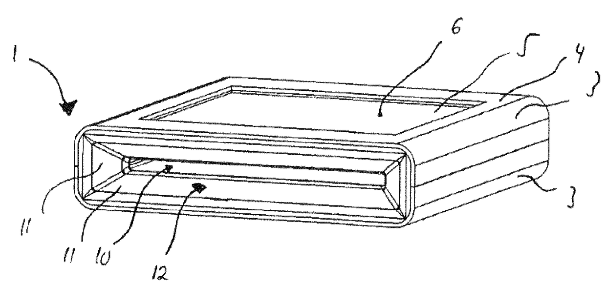
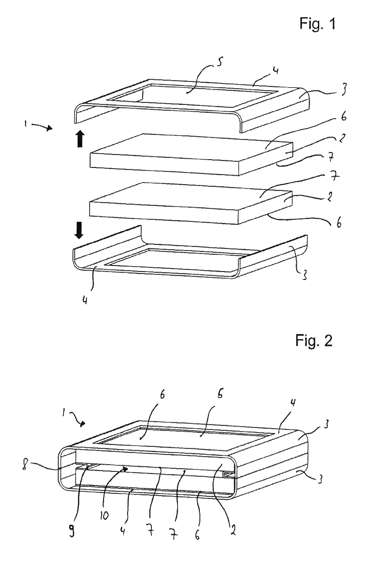
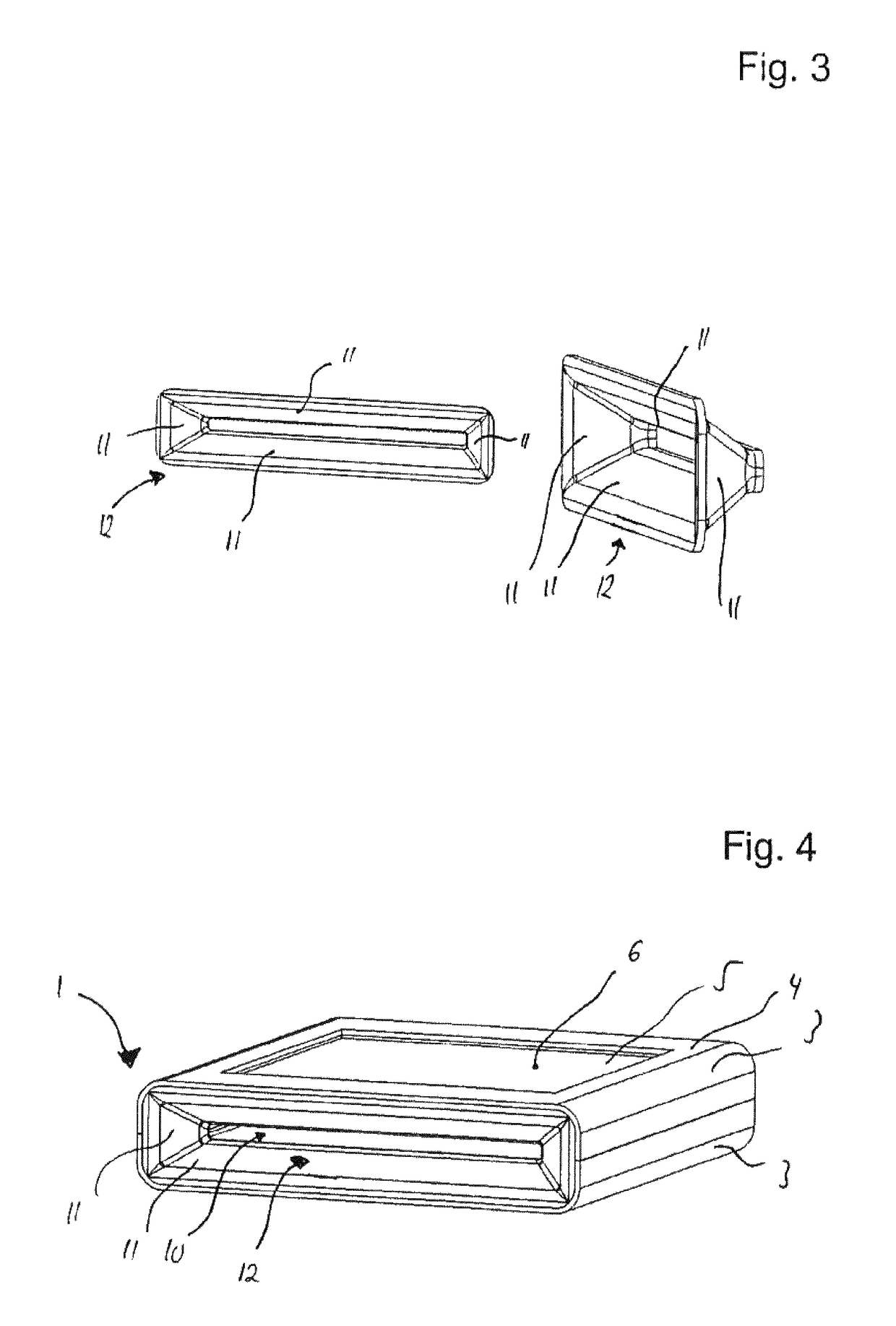
[0058]FIG. 1 shows an exploded illustration of a thermoelectric device 1. The thermoelectric device 1 includes substantially of a flat tube 8 that is formed from two U-shaped flat tube pieces 3. Two thermoelectric modules 2 are arranged between these U-shaped flat tube pieces 3. The thermoelectric modules have substantially two first walls 6, 7 lying parallel to one another. The two walls 7 of thermoelectric modules 2 here face one another. The respective other walls 6 of thermoelectric modules 2 face away from one another toward the outer side of thermoelectric device 1.

[0059]The two U-shaped flat tube pieces 3 each have a cutout 5, which is introduced in wall 4 of U-shaped flat tube piece 3. In the assembled state, walls 6 of thermoelectric module 2 are in thermally conductive communication with wall 4 of U-shaped flat tube piece 3. Methods such as welding, gluing, or soldering can be used to connect thermoelectric module 2 with U-shaped flat tube piece 3.

[0060]FIG. 2 shows the el...


PUM


Abstract

A thermoelectric device having a flat tube, a first thermoelectric module, and a second thermoelectric module. The thermoelectric modules each have a housing that includes at least two opposite first walls. A plurality of thermoelectric elements is arranged between the first walls of the housing. The thermoelectric elements have opposite surfaces, each of which is in thermal contact with one of the first walls of the housing of the thermoelectric module.

Description

[0001]This nonprovisional application is a continuation of International Application No. PCT / EP2013 / 066968, which was filed on Aug. 14, 2013, and which claims priority to German Patent Application No. DE 10 2012 214 702.0, which was filed in Germany on Aug. 17, 2012, and which are both herein incorporated by reference.BACKGROUND OF THE INVENTION[0002]Field of the Invention[0003]The present invention relates to a thermoelectric device having a flat tube and a first thermoelectric module and a second thermoelectric module, whereby the thermoelectric modules each have a housing with at least two opposite first walls, whereby a plurality of thermoelectric elements are arranged between the first walls of the housing, whereby the thermoelectric elements have opposite surfaces, which in each case are in thermal contact with one of the first walls of the housing of the thermoelectric module. In addition, the invention relates to an arrangement of a thermoelectric device in a heat exchanger....

Claims


Application Information

Patent Timeline
Patent Type & Authority Patents(United States)
IPC IPC(8): H01L35/32F01N5/02H01L35/30
CPCH01L35/32H01L35/30F01N5/025Y02T10/16Y02T10/12H10N10/17H10N10/13
Inventor HIMMER, THOMAS
Owner MAHLE INT GMBH
Why Eureka
Try Eureka