Hip fixation with load-controlled dynamization

a technology of load-controlled dynamization and hip fixation, which is applied in the direction of osteosynthesis devices, bone plates, fasteners, etc., can solve the problem that neither approach may be optimal

Active Publication Date: 2018-09-25
ACUMED
View PDF118 Cites 3 Cited by
  • Summary
  • Abstract
  • Description
  • Claims
  • Application Information

AI Technical Summary

Benefits of technology

[0007]The hip joint is a synovial joint formed by articulation of the head of the femur (the femoral head) with the acetabulum of the pelvis. The hip joint(s) supports the weight of the body when a person is standing, walking, or running, among others.

Problems solved by technology

However, neither approach may be optimal.

Method used


Image

  • Hip fixation with load-controlled dynamization
  • Hip fixation with load-controlled dynamization
  • Hip fixation with load-controlled dynamization

Examples


example 1

ion System with a Nail

[0070]This example describes another exemplary hip fixation system 140 including a nail 100 (as a support member 58a), and a fixation element 56 attached to a deformable member 60; see FIG. 6.

[0071]Hip fixation system 140 may include any suitable combination of features described above, such as in Section I for system 50 (e.g., see FIGS. 1-5), and elsewhere in the present disclosure. However, system 140 may not utilize an outer support member 58b (compare FIGS. 1 and 6).

[0072]Fixation element 56 is pre-attached to a deformable member 60 that is positioned for contact with a stop member 61. The stop member is attached to nail and is adjustably positionable along the long axis of the nail by turning at least a portion of the stop member, to advance the stop member into an operative position that restricts rotation of the fixation element about its long axis and obstructs axial travel of the deformable member after the nail and fixation element have been placed in...

example 2

ion System with a Side Plate Having a Barrel Portion

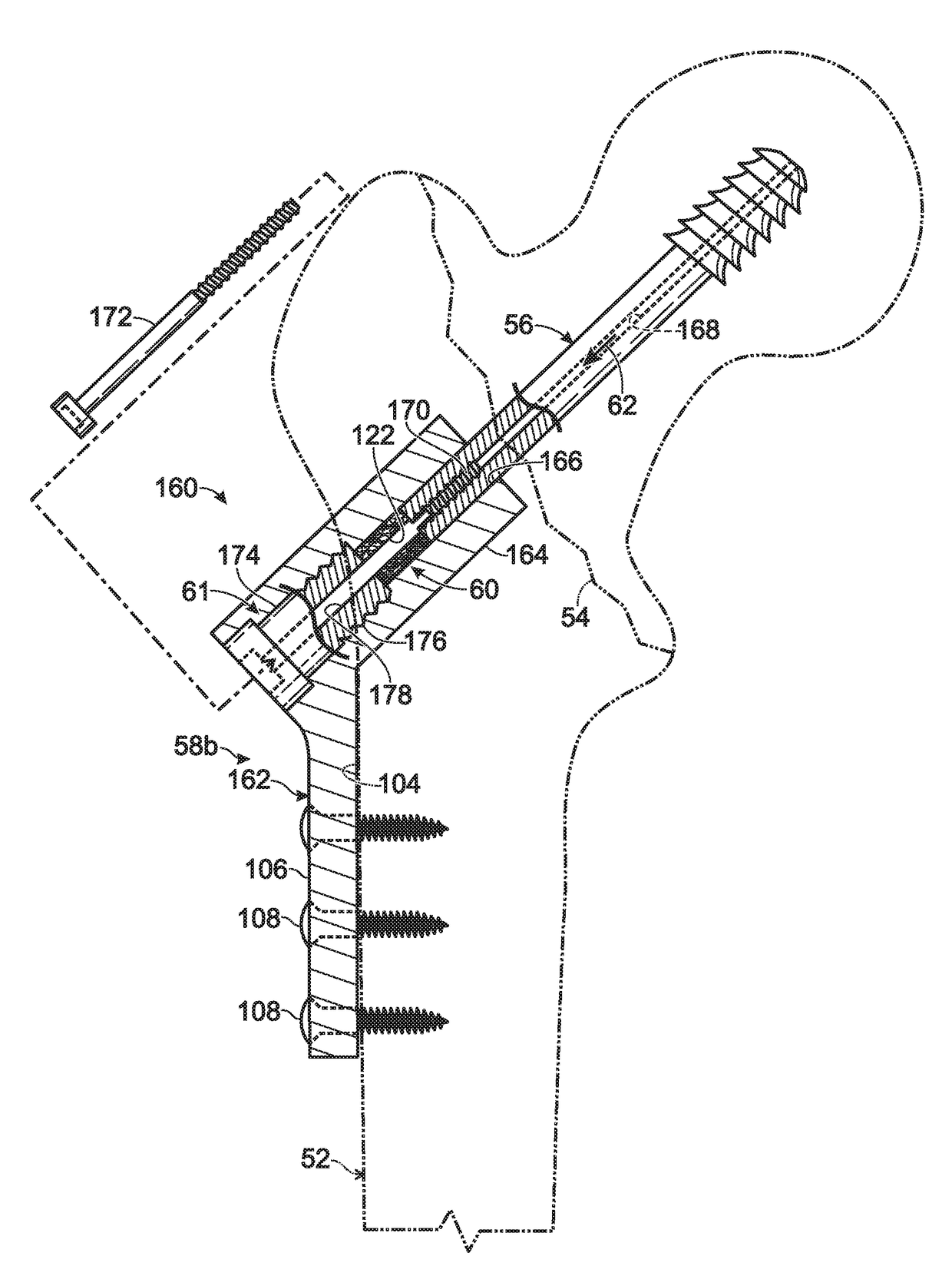
[0075]This example describes an exemplary hip fixation system 160 including a side plate 162 (as a support member 58b) having a barrel portion 164 that extends into femur 52, and also including a deformable member 60 disposed in barrel portion 164; see FIG. 7.

[0076]Hip fixation system 160 may include any suitable combination of features described above, such as in Section I for system 50 (e.g., see FIGS. 1-5), and elsewhere in the present disclosure (e.g., Example 1). However, system 160 may not utilize an inner support member 58a (compare FIGS. 1, 6, and 7). System 160 may be suitable for fixation of an intertrochanteric fracture 54, among others.

[0077]Side plate 162 (also called a plate device) may include a mounting portion 106 from which barrel portion 164 projects. The mounting portion may be configured to be mounted on the proximal femur, such as mounted on a lateral surface region provided by lateral cortex 104. The mounting...

example 3

ion Systems for Neck Fractures

[0083]This example describes exemplary hip fixation systems 180, 190 each having a deformable member 60 and configured to fix femoral neck fractures; see FIGS. 8-11.

[0084]Hip fixation systems 180, 190 may include any suitable combination of features described above, such as in Section I for system 50 (e.g., see FIGS. 1-5), and elsewhere in the present disclosure (e.g., see Example 1). However, systems 180, 190 each may (or may not) include a plurality of fixation elements 56, which may extend parallel to one another after placement into the femur. Each fixation element 56 may or may not be cannulated. Each fixation element 56 may have a head 192 that engages a lateral surface region of the femur, to block inward travel of the fixation element into the femur, such that the fixation element applies compression to the femur at fracture 54 during installation. Systems 180, 190 may include a support member 58b in the form of a buttress plate that is mounted ...


PUM


Abstract

System, including methods and apparatus, for hip fixation with load-controlled dynamization. In exemplary embodiments, the system may comprise a fixation element, such as a screw, configured to be placed into a proximal femur of a subject, with a leading end of the fixation element anchored in a head of the proximal femur. The system also may comprise a stop member configured to be connected (e.g., via a nail or plate) to the proximal femur. The system further may comprise a deformable member configured to be irreversibly deformed by compressive force exerted on at least a portion of the deformable member by the fixation element and the stop member in response to a load applied to the proximal femur by the subject, such that the fixation element and the stop member move relative to one another parallel to a long axis of the fixation element.

Description

CROSS-REFERENCES TO PRIORITY APPLICATIONS[0001]This application is a continuation-in-part of the following U.S. patent applications: U.S. patent application Ser. No. 14 / 565,105, filed Dec. 9, 2014; U.S. patent application Ser. No. 14 / 565,116, filed Dec. 9, 2014; U.S. patent application Ser. No. 14 / 566,350, filed Dec. 10, 2014; and U.S. patent application Ser. No. 14 / 706,922, filed May 7, 2015.[0002]U.S. patent application Ser. No. 14 / 565,105, in turn, is based upon and claims the benefit under 35 U.S.C. § 119(e) of U.S. Provisional Patent Application Ser. No. 61 / 913,593, filed Dec. 9, 2013.[0003]U.S. patent application Ser. No. 14 / 565,116, in turn, is based upon and claims the benefit under 35 U.S.C. § 119(e) of U.S. Provisional Patent Application Ser. No. 61 / 913,611, filed Dec. 9, 2013.[0004]U.S. patent application Ser. No. 14 / 566,350, in turn, is a continuation-in-part of U.S. patent application Ser. No. 14 / 565,105 and U.S. patent application Ser. No. 14 / 565,116, with priority cla...

Claims


Application Information

Patent Timeline
Patent Type & Authority Patents(United States)
IPC IPC(8): A61B17/70A61B17/86A61B17/80A61B17/72A61B17/74
CPCA61B17/725A61B17/746A61B17/863A61B17/8038A61B17/8061A61B17/748
Inventor EHMKE, LARRY W.
Owner ACUMED
Why Eureka
Try Eureka