
Plate-based compliant hip fixation system

a plate-based, compliant technology, applied in the field of plate-based compliant hip fixation system, can solve the problems of femoral head damage, fixation device not always providing a successful outcome,

Active Publication Date: 2016-10-11
ACUMED
View PDF101 Cites 1 Cited by
  • Summary
  • Abstract
  • Description
  • Claims
  • Application Information

AI Technical Summary

Benefits of technology

[0002]The hip joint is a synovial joint formed by articulation of the head of the femur with the acetabulum of the pelvis. The hip joint(s) supports the weight of the body when a person is standing, walking, or running, among others.
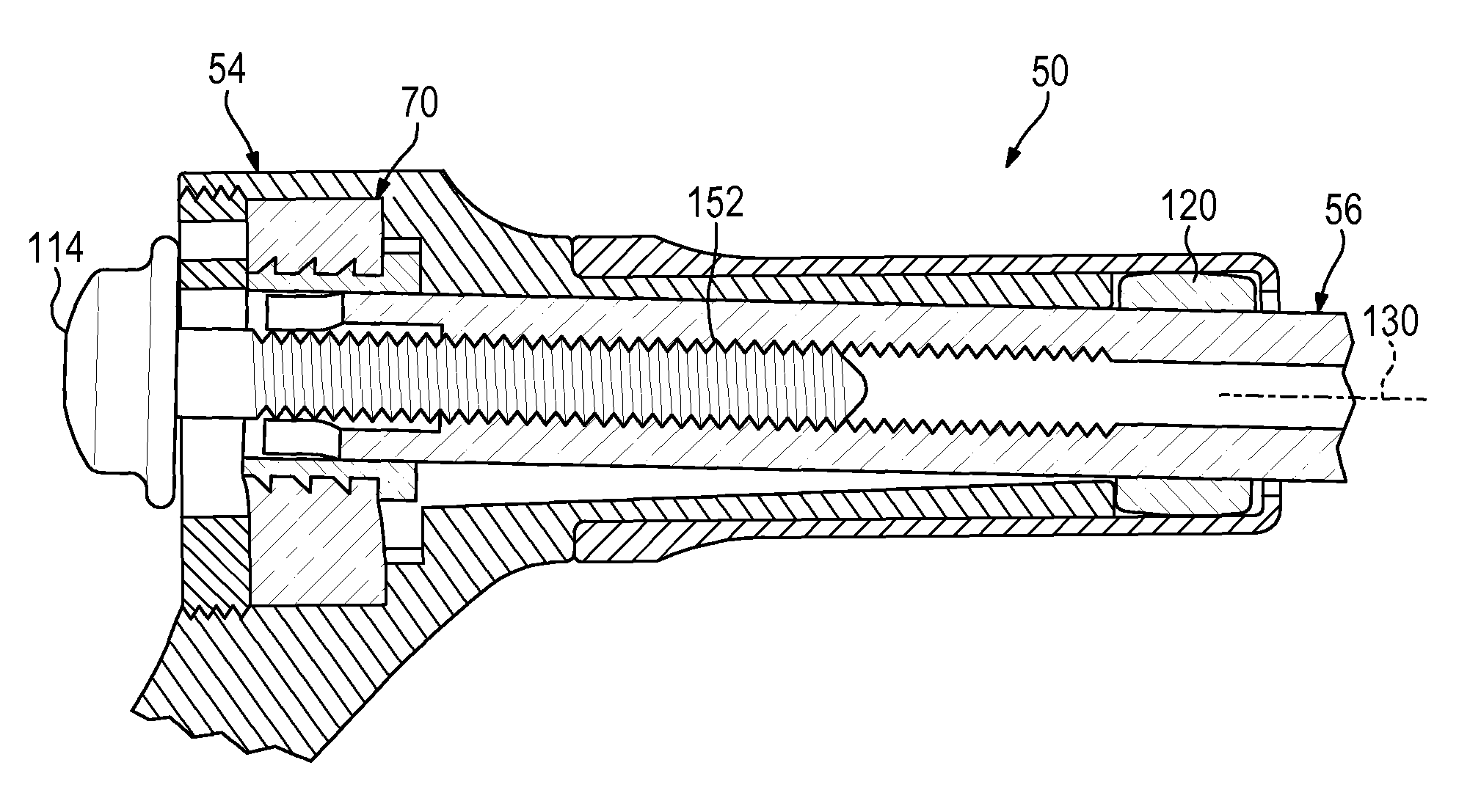
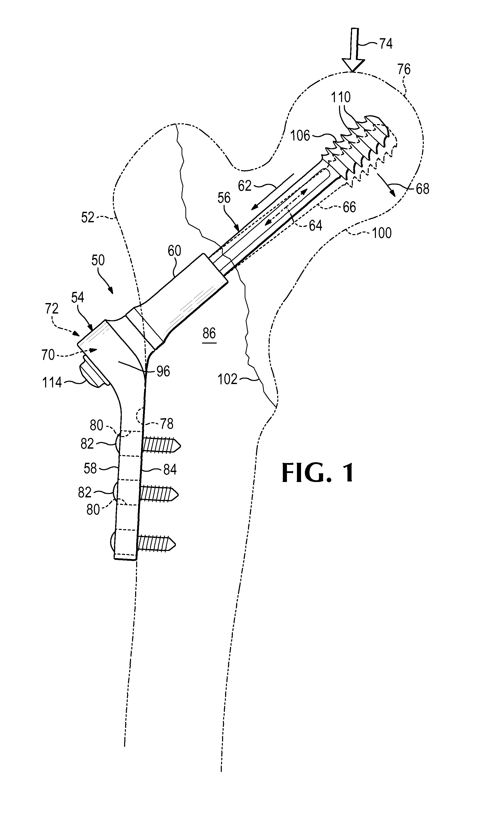
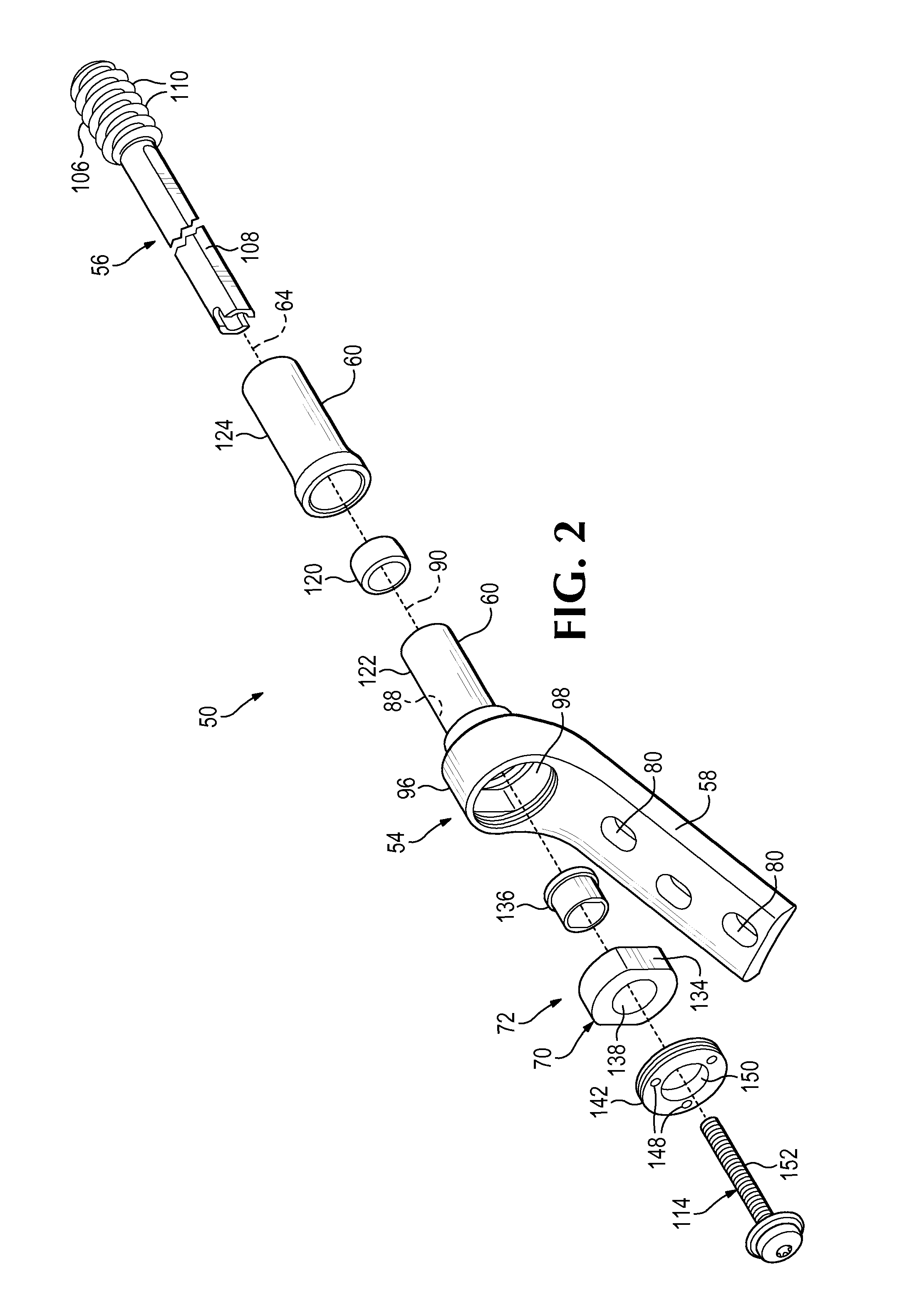
[0005]The screw may not be fixed with respect to the barrel of the side plate. Instead, the screw may be permitted to slide parallel to its long axis in the barrel. Accordingly, the screw can migrate laterally (anatomically) after installation, for dynamic compression of the fracture, which can encourage and improve fracture healing.
[0006]The ability of the screw to slide along its axis can improve performance dramatically. Nevertheless, the fixation device does not always provide a successful outcome. In some cases, the femoral head is damaged by cut-out, where migration of the femoral head relative to the screw causes the screw to project through the articular surface of the femoral head, and / or to split the femoral head.

Problems solved by technology

Nevertheless, the fixation device does not always provide a successful outcome.
In some cases, the femoral head is damaged by cut-out, where migration of the femoral head relative to the screw causes the screw to project through the articular surface of the femoral head, and / or to split the femoral head.

Method used


Image

  • Plate-based compliant hip fixation system
  • Plate-based compliant hip fixation system
  • Plate-based compliant hip fixation system

Examples


example 1

Hip Fixation System with Swaged Barrel Portion

[0074]This example describes an exemplary hip fixation system 160 with a one-piece barrel portion 60 having a swaged end 162 that captures a bearing element 120 inside the barrel portion; see FIGS. 6 and 7.

[0075]Hip fixation system 160 may be structured generally as described above for system 50 (see Section I). However, barrel portion 60 may be generated initially with a cylindrical flange 164 (shown in phantom outline in FIG. 6) that is sized to receive bearing element 120. A lip portion of flange 164 then may be deformed, such as rolled radially inward, to prevent removal of the bearing element from channel 88.

[0076]Barrel portion 60 and bearing element 120 may cooperate to prevent rotation of fixation element 56 about its long axis and to restrict angular motion of the fixation element to one plane of a set of three mutually orthogonal planes (see FIG. 7). Barrel portion 60 may define one or more inside flats 166 that contact one or ...

example 2

Hip Fixation System Having a Perforated Compliant Member

[0077]This example describes exemplary compliant hip fixation systems 180, 190 having a perforated compliant member 192 or 194 that contacts the fixation element; see FIGS. 8-10.

[0078]Fixation systems 180 and 190 may have any combination of the elements and features described elsewhere herein. For example, each system may have a compression screw and a retainer (see FIGS. 2 and 4), which are not shown here to simplify the presentation.

[0079]Compliant member 192 may define a central opening 196 in which fixation element 56 can slide. The compliant member may have a low coefficient of friction with the fixation element, which allows the compliant member and fixation element to slideably contact one another. For example, compliant member 192 may be formed of metal or smooth, relatively hard plastic. The wall of central opening 196 may define flats 198 that cooperate with flats 108 of fixation element 56.

[0080]Compliant member 192 ...

example 3

Hip Fixation System with a Barrel Portion as a Bearing Element

[0082]This example describes an exemplary compliant hip fixation system 220 having a barrel portion 60 with an inside wall region 222 that slideably contacts a fixation element 56; see FIG. 11.

[0083]Fixation system 220 may be structured generally as described above for hip fixation system 180 (see FIGS. 8 and 10). However, bearing element 120 may be omitted. Instead, fixation element 56 may movably contact wall region 222 formed integrally with or fixed in relation to barrel portion 60 and, optionally, formed integrally with mounting portion 58. Wall region 222 may (or may not) be shaped to restrict rotation of fixation element 56 about its long axis and / or to restrict angular motion of the fixation element to one plane of a set of three mutually orthogonal planes.


PUM


Abstract

System, including methods, devices, and kits, for hip fixation. The system may include a fixation element configured to be placed obliquely into a proximal femur and anchored in a head of the proximal femur. The system also may include a plate member including (a) a mounting portion configured to be placed on and attached to a lateral cortex of the proximal femur and (b) a barrel portion configured to be placed into a lateral region of the proximal femur and positioned around a portion of the fixation element. The system further may include a compliant member positioned or positionable at least partially in the plate member and configured to be reversibly deformed in response to a load applied to the head of the proximal femur, to change an angular orientation of the fixation element with respect to the plate member.

Description

CROSS-REFERENCE TO PRIORITY APPLICATION[0001]This application is based upon and claims the benefit under 35 U.S.C. §119(e) of U.S. Provisional Patent Application Ser. No. 61 / 913,593, filed Dec. 9, 2013, which is incorporated herein by reference in its entirety for all purposes.INTRODUCTION[0002]The hip joint is a synovial joint formed by articulation of the head of the femur with the acetabulum of the pelvis. The hip joint(s) supports the weight of the body when a person is standing, walking, or running, among others.[0003]Trauma to the femur can fracture the femur near the hip joint. Depending on the position and severity of fracture, the femoral head may be replaced with a prosthesis, or the bone may be stabilized with an implanted fixation device to hold the femoral head in position while the femur heals.[0004]A plate-based fixation device involving a side plate and a sliding screw is commonly utilized for fixation. The side plate has a barrel portion for receiving a portion of t...

Claims


Application Information

Patent Timeline
Patent Type & Authority Patents(United States)
IPC IPC(8): A61B17/56A61B17/74
CPCA61B17/748A61B17/746
Inventor EHMKE, LARRY W.HORST, STEVEN P.SOMMERS, MARK B.CONLEY, BRIAN R.
Owner ACUMED
Learn More