Hip fixation system with a compliant fixation element

a fixation element and fixation device technology, applied in the direction of internal osteosynthesis, internal osteosynthesis, osteosynthesis devices, etc., can solve the problems of femoral head damage, fixation device not always providing a successful outcome, etc., and achieve the effect of reducing the deformation of the compliant region

Active Publication Date: 2016-09-06
ACUMED
View PDF101 Cites 6 Cited by
  • Summary
  • Abstract
  • Description
  • Claims
  • Application Information

AI Technical Summary

Benefits of technology

[0002]The hip joint is a synovial joint formed by articulation of the head of the proximal femur and the acetabulum of the pelvis. The hip joint(s) supports the weight of the body when a person is standing, walking, or running, among others.
[0004]A nail-based fixation device involving an intramedullary nail and a screw is commonly utilized for fixation. The nail is placed axially into the proximal femur from a proximal end thereof. Then, the screw is inserted obliquely into the proximal femur from a lateral side thereof, through the nail and the femoral neck, and into the femoral head. The screw may be placed at an angle of about 125 degrees with respect to the nail, to account for the angle between the femoral head / neck and the femoral shaft. The screw and the nail both generally span the fracture. Accordingly, the screw can transfer the load from the femoral head to the nail, which can stabilize the fractured femur more effectively and improve healing.
[0006]The screw may not be fixed with respect to the nail or with respect to the barrel of the side plate. Instead, the screw may be permitted to slide parallel to its long axis in the nail or barrel. More particularly, the screw may be allowed to migrate laterally (anatomically) after installation, for dynamic compression of the fracture, which can encourage and improve fracture healing.
[0007]The ability of the screw to migrate can improve performance dramatically. However, the fixation device does not always provide a successful outcome. In some cases, the femoral head is damaged by cut-out, where migration of the femoral head relative to the screw causes the screw to project through the articular surface of the femoral head, and / or to split the femoral head.

Problems solved by technology

However, the fixation device does not always provide a successful outcome.
In some cases, the femoral head is damaged by cut-out, where migration of the femoral head relative to the screw causes the screw to project through the articular surface of the femoral head, and / or to split the femoral head.

Method used


Image

  • Hip fixation system with a compliant fixation element
  • Hip fixation system with a compliant fixation element
  • Hip fixation system with a compliant fixation element

Examples


example 1

Fixation Elements with Flexible Shafts

[0098]This example describes exemplary fixation elements for the hip fixation systems of Section I, with each fixation element having a shaft with a compliant region forming only a longitudinal portion of the shaft; see FIGS. 9-11.

[0099]FIG. 9 shows a fixation element 56 defining an opening in the form of a sinuous helical slit 180 that forms a compliant region 68. The slit may provide communication between an axial bore and the exterior of the fixation element. Slit 180 may create interlocking features composed of tabs 182 located in complementary recesses 184, which permit flexion of the element's shaft and torque transmission through the shaft.

[0100]FIG. 10 shows another exemplary fixation element 56 for the systems of Section I. The element has a neck or waist 190 that forms a compliant region 68 of the fixation element. Neck may represent narrowing of shaft 64 that is axisymmetric, bilateral, or unilateral. In some embodiments one or more i...

example 2

Fixation Elements with a Flexible Bone-Securing Portion

[0102]This example describes exemplary fixation elements for the hip fixation systems of Section I, with each fixation element having a flexible bone-securing portion formed at a leading end region of the element; see FIGS. 12-20.

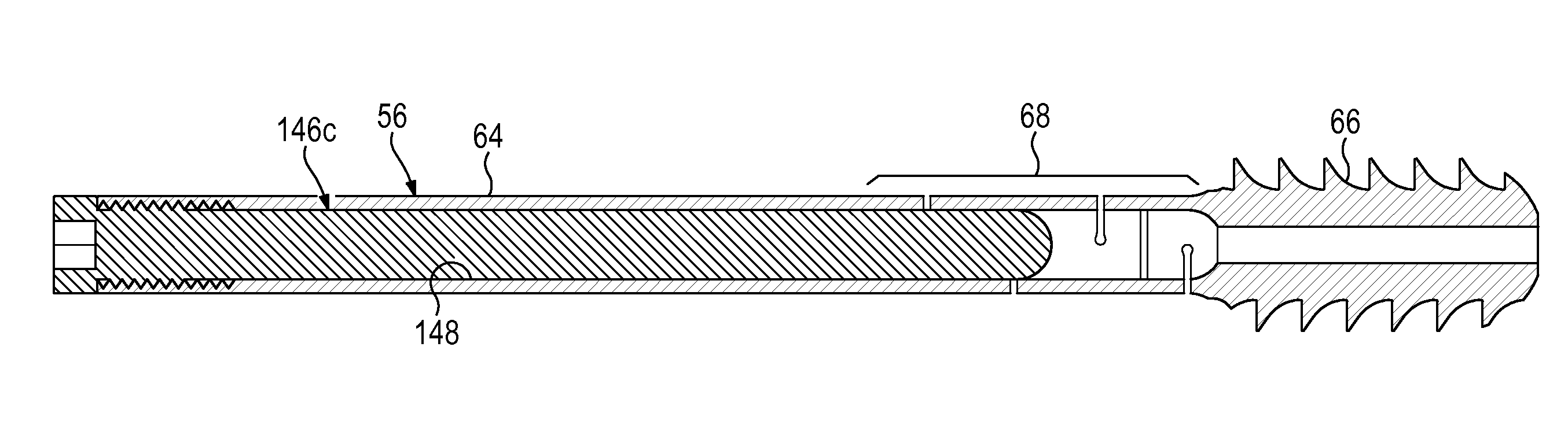
[0103]FIGS. 12-14 show a fixation element 56 with a bone-securing portion 66 having a compliant region 68 produced by a flexible blade 220. The blade extends from shaft 64 and may (or may not) be wider than the shaft to form a paddle-shaped element. The blade has a body 222 and a row of teeth 224 projecting from a center line of the body, with the row arranged parallel to the long axis of the fixation element. The size of gaps 226 between the teeth may determine how far the blade can be flexed downward (or upward); contact between the teeth, produced by flexing the blade, may establish a limit of downward flexion. Blade 220 may be configured to deform substantially in one plane of a set of three mutuall...

example 3

Fixation Elements with Internal Compliant Region

[0106]This example describes fixation elements 56 for the hip fixation systems of Section I, with each fixation element including a bone-securing portion 66 having an internal compliant region; see FIGS. 21-23.

[0107]FIG. 21 shows an exemplary three-part fixation element 56 having a shaft 64 and a compliant bone-securing portion 66. The bone-securing portion has a bone-engaging region 260 surrounded by a core 262, and separated from the core by a reversibly deformable compliant member 264 that forms compliant region 68 of the fixation element. Shaft 64 may or may not be formed integrally with core 262. Compliant member 264 may surround core 262 and may be structured as a layer (e.g., a tubular layer) disposed between core 262 and bone-engaging region 260. The bone-engaging region may have any suitable structure for anchoring the fixation element in bone, such as an external thread 266, barbs, a blade, teeth, etc. Bone-engaging region 26...


PUM


Abstract

System, including methods, devices, and kits, for hip fixation. The system may include a support member defining an aperture and including an intramedullary nail for a proximal femur or a plate member for a proximal femur. The system also may include a fixation element having a compliant region and configured to be received in the aperture of the support member such that the fixation element extends out of the support member from the aperture and into a head of the proximal femur and is slideable with respect to the support member along a long axis defined by the fixation element. The system further may include a set of stiffening inserts each insertable into the fixation element and configured to stiffen the compliant region differently from one another.

Description

CROSS-REFERENCES TO PRIORITY APPLICATIONS[0001]This application is based upon and claims the benefit under 35 U.S.C. §119(e) of U.S. Provisional Patent Application Ser. No. 61 / 914,180, filed Dec. 10, 2013, and is a continuation-in-part of U.S. patent application Ser. No. 14 / 565,105, filed Dec. 9, 2014; and U.S. patent application Ser. No. 14 / 565,116, filed Dec. 9, 2014. The Ser. No. 14 / 565,105 application, in turn, claims priority from U.S. Provisional Patent Application Ser. No. 61 / 913,593, filed Dec. 9, 2013. The Ser. No. 14 / 565,116 application, in turn, claims priority from U.S. Provisional Patent Application Ser. No. 61 / 913,611, filed Dec. 9, 2013. Each of these priority applications is incorporated herein by reference in its entirety for all purposesINTRODUCTION[0002]The hip joint is a synovial joint formed by articulation of the head of the proximal femur and the acetabulum of the pelvis. The hip joint(s) supports the weight of the body when a person is standing, walking, or r...

Claims


Application Information

Patent Timeline
Patent Type & Authority Patents(United States)
IPC IPC(8): A61B17/74
CPCA61B17/746A61B17/744
Inventor EHMKE, LARRY W.HORST, STEVEN P.SOMMERS, MARK B.CONLEY, BRIAN R.
Owner ACUMED
Why Eureka
Try Eureka