AI technical title is built by Patsnap AI team. It summarizes the technical point description of the patent document.
a technology of nosecone and microneedle, which is applied in the direction of microneedles, infusion needles, other medical devices, etc., can solve the problems of no other microneedle cartridges incorporating the use of absorbent materials, and current motorized microneedling devices are not capable of preventing fluids from exiting, so as to achieve convenient use, safe use of stiff metal, and adequate connection
Active Publication Date: 2018-11-27
ESTHETIC MEDICAL INC
View PDF4 Cites 0 Cited by
Summary
Abstract
Description
Claims
Application Information
AI Technical Summary
This helps you quickly interpret patents by identifying the three key elements:
Problems solved by technology
Method used
Benefits of technology
Benefits of technology
[0020]Based on the health risks posed to patients by virtue of possible exposure to blood borne pathogens trapped inside the motorized microneedling device and then potentially transmitted to the next patient, it is apparent that current motorized microneedling devices are not capable of preventing fluids from exiting the needle cartridge and entering the device. In order to prevent this, a new cartridge and nose cone assembly system is presented. Three features are combined into a microneedling cartridge interface that prevents the transmission of any fluid from microneedle cartridge into the motorized microneedling device as well as affording the ability to remove and autoclave sterilize the portion of the motorized microneedling device in contact with the microneedle cartridge. Additionally, a polymer reciprocal piston rod affords the ability to provide an adequate connection to the microneedle cartridge receiver while also allowing the polymer reciprocal piston rod to be replaced in the event of damage or wear. The microneedle cartridge apparatus is constructed with two internal baffle cylinders and two absorbent gaskets that prevent any liquid from traveling from the gap between the outer cartridge wall and the inner microneedle array block, through the cartridge and into the motorized microneedling device via the gap between the outer cartridge connection to the motorized device and the central rod affixing the microneedling array. These absorbent gaskets prevent capillary action from facilitating the travel of liquid through the microneedle cartridge and are treated with an antimicrobial agent to marginalize any pathogen coming into contact with the gaskets. Currently, there are no other microneedle cartridges incorporating the use of absorbent material to trap liquids. One inner concentric cylinder slides inside a tightly machined gap between the outer cylinder allowing the central rod with the microneedle array attached to move freely through the outer cartridge connection housing while simultaneously preventing liquids from traversing the gap between them as they are arranged with the height of the smaller central cylinder being greater than the distance traveled outwards into the skin by the central rod attached to the microneedle array. In this way the path through the microneedle cartridge is comprised of two 180 degree turns with absorbent material gaskets at each turn to absorb any liquid that could possibly travel this path. The microneedle cartridge itself is attached to the nose cone of the motorized microneedling device by means of male to female threads. As the microneedle cartridge was designed to prevent fluids from being able to enter the motorized microneedling device, this microneedle cartridge is able to safely utilize a stiff metal return spring maximizing the depth the microneedle array can efficiently enter and withdraw from the skin without tearing it or damaging the electric motor. In order to provide another backup system to further prevent liquids from entering the motor area of the microneedle device, a thin silicone gasket is attached on the end of the central rod of the microneedle cartridge very close to where it connects with the polymer reciprocal piston rod. This junction is where the microneedle cartridge is attached to the motorized microneedling device.
[0021]To complete the microneedle cartridge interface system, the nose cone section of the motorized microneedling device is able to be removed from the rest of the device by means of male to female threads. While the absorbent gaskets, concentric cylinders and restricted path for liquids incorporated into the design of microneedle cartridge prevents liquids from entering the nosecone section from the microneedle array, in the event any liquids could somehow enter the nosecone, the nose cone can be removed, autoclaved sterilized, and replaced prior to the next patient. The removable nose cone is designed with a tight gap tolerance between the nose cone central opening and the reciprocal piston rod of the microneedling device to effectively contain and isolate within itself, any particulate or liquid that may somehow enter the nose cone. By closely adapting the shape of the connecting end of the reciprocal piston rod to the piston rod housing, the ability for liquid or particulate matter to enter the piston rod housing is significantly reduced. By constructing the reciprocal piston rod out of dense polymer or some equivalent material, it is able to provide a secure connection between the receiver end of the microneedle cartridge and the polymer reciprocal piston rod. This is facilitated by the addition of ribbed grooves stamped into the receiver cradle of the microneedle cartridge apparatus. Unlike many metal or plastic reciprocal piston rods, this polymer reciprocal polymer reciprocal piston rod is not a traditional rod shape but, rather, is a cup shaped disk that provides a floor and walls that closely adapt to the device housing. As this rod is actually shaped as a cup, this provides yet another barrier for any liquid or particulate to enter the device. Additionally, the polymer reciprocal piston rod can easily be replaced if it becomes worn or damaged. In order to facilitate patient efficiency and the time necessary to autoclave sterilize the nose cone, multiple nose cones are provided with each system so that the operator has access to a sterile nosecone while the previously used nosecone is being sterilized.
[0022]Together, as one microneedle cartridge interface system, the twin baffle cylinders microneedle cartridge apparatus with fabric gaskets, the removable, autoclavable, nose cone apparatus and the closely adapted polymer reciprocal, cup-shaped piston rod apparatus, as well as the connection gasket, provide the operator the ability to safely microneedle a patient by greatly reducing the chance of cross-contamination, autoclave the portion of the device that comes into contact with the microneedle cartridge, and easily replace a worn or damaged reciprocal piston rod.
Problems solved by technology
Based on the health risks posed to patients by virtue of possible exposure to blood borne pathogens trapped inside the motorized microneedling device and then potentially transmitted to the next patient, it is apparent that current motorized microneedling devices are not capable of preventing fluids from exiting the needle cartridge and entering the device.
Currently, there are no other microneedle cartridges incorporating the use of absorbent material to trap liquids.
Method used
Image
Click on the blue label to locate the original text in one second.
Reading with bidirectional positioning of images and text.
Examples
Embodiment Construction
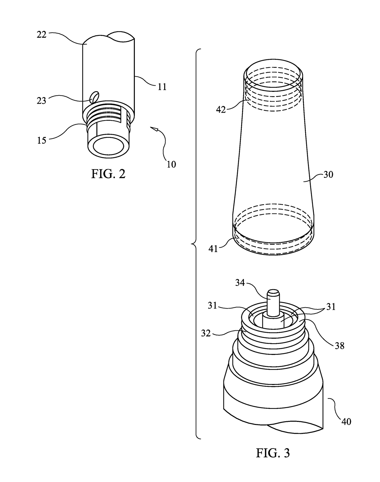
[0034]FIG. 6 illustrates the general configuration of a microneedling pen or microneedling device adapted to employ the present invention. Microneedling device body 40 contains a power source, an electric motor moving a high speed reciprocating piston, and speed and depth controls. Microneedling cartridge 10 comprises an embodiment of the present invention. Nosecone 30 joins the device body 40 and the cartridge 10.
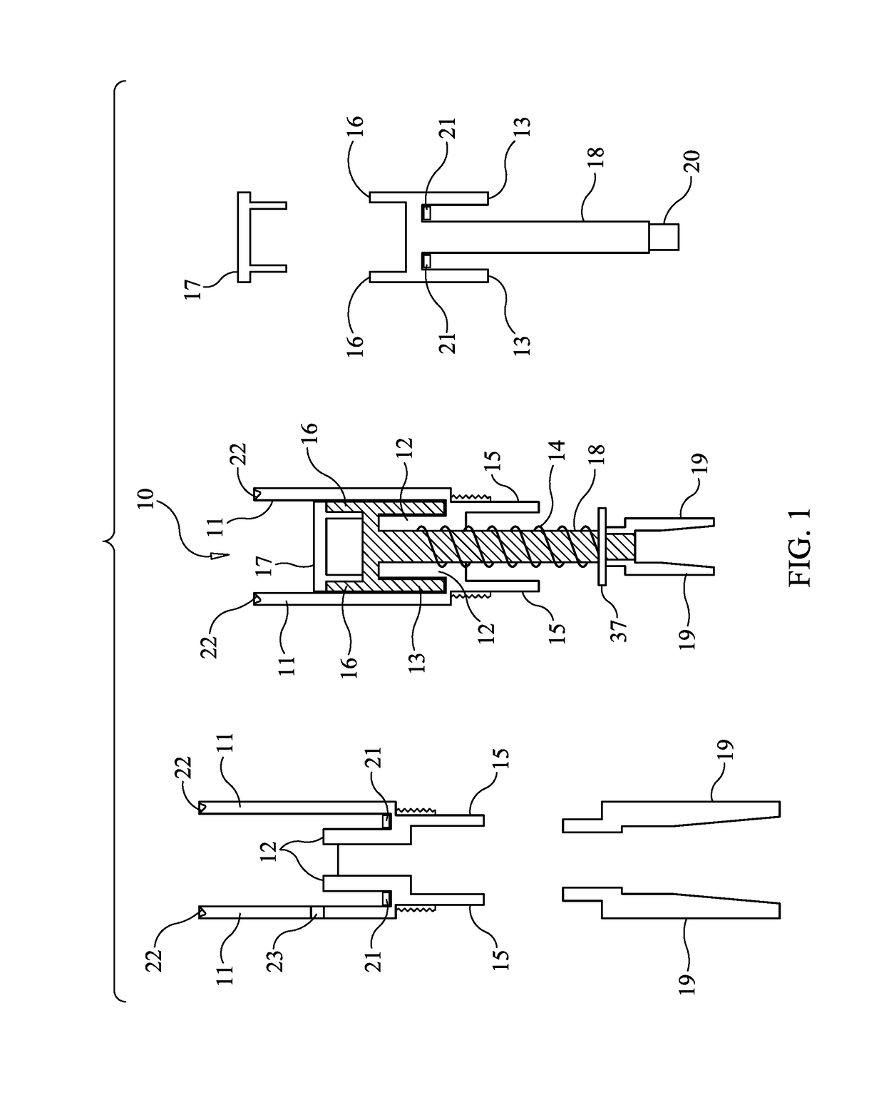
[0035]FIG. 1 is a schematic diagram illustrating the components and assembly of the microneedle cartridge apparatus 10 designed to prevent the transmission of bodily fluids in accordance with one embodiment of the present invention. The central figure shows the cartridge apparatus, with some of the components broken out and repeated on the left and right figures. Microneedle cartridge apparatus 10 includes outer cartridge cylinder 11, which provides support and isolation for internal components. Attached to, and contiguous with outer cartridge cylinder 11 is inner baffle c...
PUM
Abstract
A microneedle cartridge is provided comprising a pair of concentric cylinders wherein an inner cylinder supports a microneedle array block and moves up and down an inside cylinder, driven by a central rod which connects the microneedle array to a drive motor. An inner baffle cylinder fits inside the inner cylinder and surrounds the central rod, isolating the microneedle array from the internal cavity of the machine. Fabric gaskets treated with antimicrobial solution are placed at the locations where the inner baffle cylinder meets the inner cylinder and where the inner cylinder meets the outer cylinder. A piston rod cradle at the bottom of the cartridge engages a cup-shaped polymer reciprocating piston rod that interacts with the device motor through a connecting metal piston. A removable, autoclavable metal nosecone covers the cartridge assembly.
Description
CROSS REFERENCE TO RELATED APPLICATIONS[0001]This application is a continuation in part of U.S. application Ser. No. 14 / 975,718, filed Dec. 19, 2015 (now U.S. Pat. No. 10,010,708), which claims the benefit of U.S. provisional patent application 62 / 094,965, filed Dec. 20, 2014.TECHNICAL FIELD OF THE INVENTION[0002]The present device components relate in general to a skin treatment protocol and, more particularly, to an apparatus, a system, and a method to deliver beneficial molecules in order to enhance the appearance of the skin while, simultaneously, prohibiting any liquid, bodily fluid, or topical product from entering into the apparatus.BACKGROUND OF THE INVENTION[0003]In modern society, much importance has been placed on physical appearance. The relative condition of a person's skin often implies health, youth, and beauty. Dermatological conditions such as acne scarring, stretch marks, surgical scars, melasma, and other conditions detract from the appearance of the skin. There h...
Claims
Application Information
Patent Timeline
Application Date:The date an application was filed.
Publication Date:The date a patent or application was officially published.
First Publication Date:The earliest publication date of a patent with the same application number.
Issue Date:Publication date of the patent grant document.
PCT Entry Date:The Entry date of PCT National Phase.
Estimated Expiry Date:The statutory expiry date of a patent right according to the Patent Law, and it is the longest term of protection that the patent right can achieve without the termination of the patent right due to other reasons(Term extension factor has been taken into account ).
Invalid Date:Actual expiry date is based on effective date or publication date of legal transaction data of invalid patent.

