Flexible display device

a display device and flexible technology, applied in the field of display devices, can solve the problems of defective electrical connections prone to occur between the terminals and the flexible printed wiring board, and achieve the effect of preventing the occurrence of defective electrical connections and ensuring the flexibility of the substrate itsel

Active Publication Date: 2008-04-15
SAMSUNG DISPLAY CO LTD +1
View PDF10 Cites 9 Cited by
  • Summary
  • Abstract
  • Description
  • Claims
  • Application Information

AI Technical Summary

Benefits of technology

[0007]The present invention has been made in view of the above, and an object of the present invention is to provide a display device capable of securing a sufficient connection between the terminals and the flexible printed wiring board without deteriorating the flexibility of the substrate itself.
[0013]The display device of the above configuration is capable of securing a sufficient connection between the terminals and the flexible printed wiring board, and preventing occurrences of defective electrical connections without deteriorating the flexibility of its substrate itself, even if the substrate is bent.

Problems solved by technology

Here, since the portion provided with the terminals is configured so as to be flexible, it is pointed out that defective electrical connections are apt to occur between the terminals and the flexible printed wiring board.

Method used


Image

  • Flexible display device
  • Flexible display device
  • Flexible display device

Examples


example 1

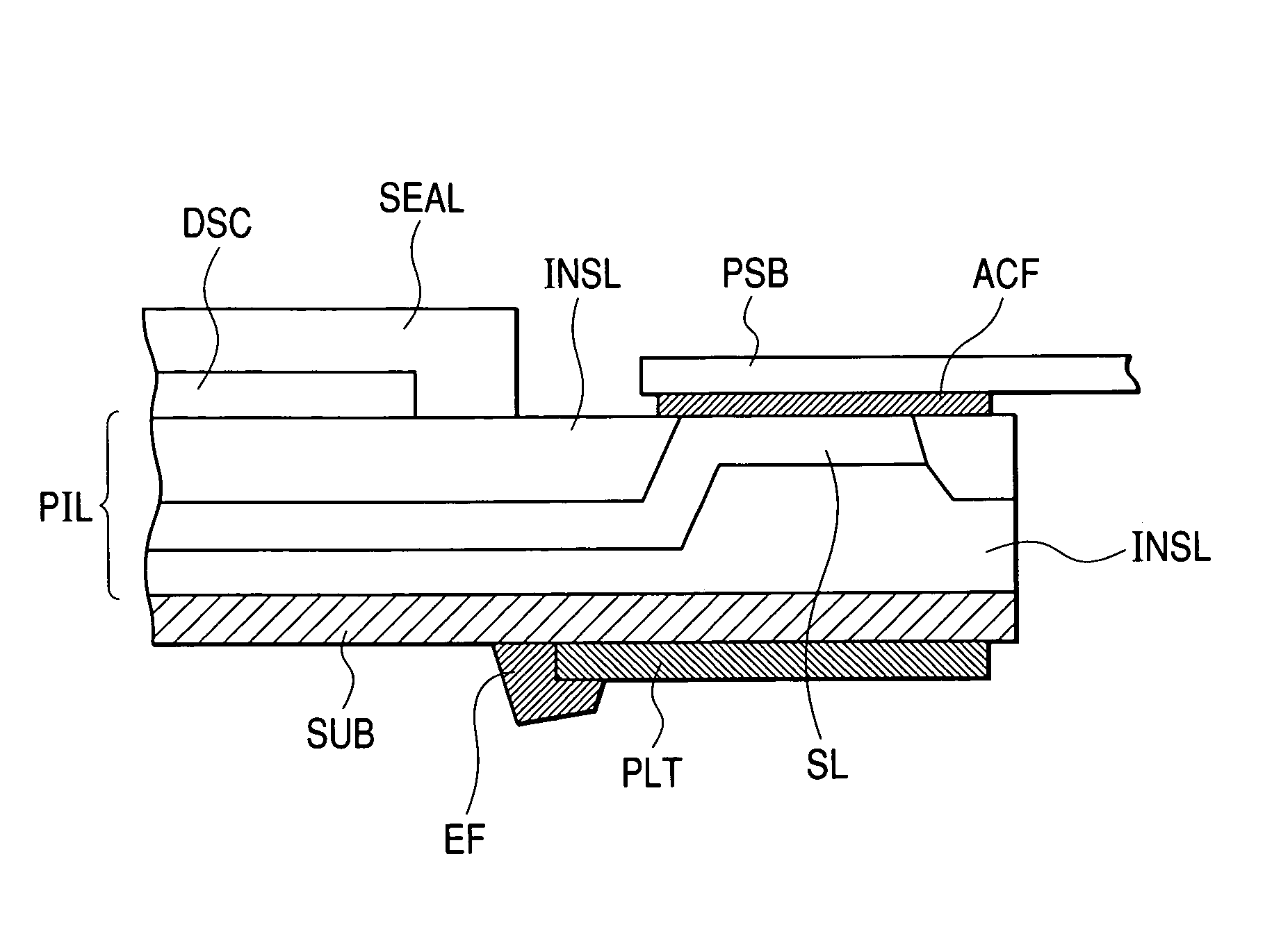
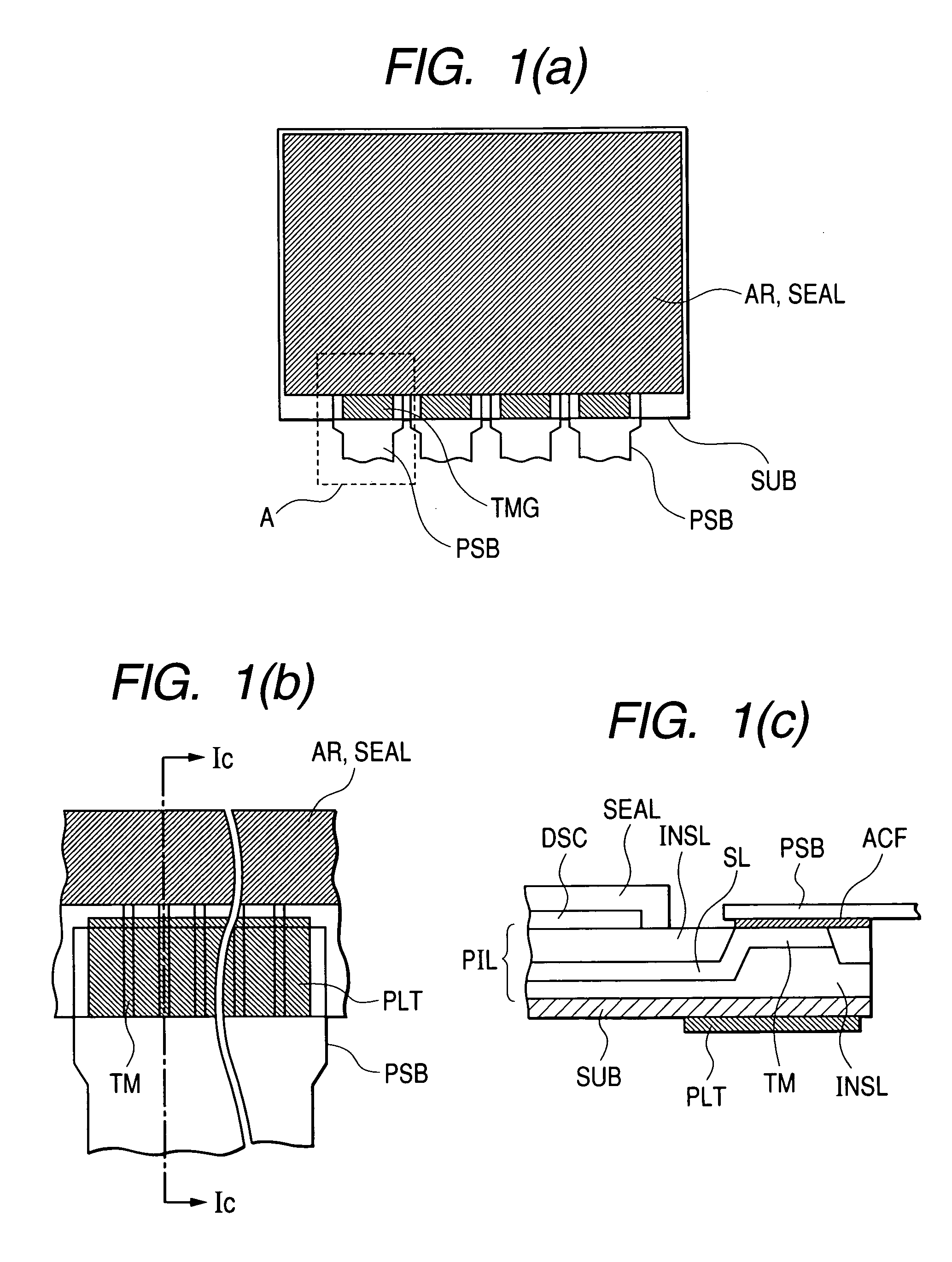
[0049]FIG. 1(b) is an enlarged plan view of an area A enclosed by broken lines in FIG. 1(a), and shows that one of the flexible wiring boards PSB is coupled to plural adjacent terminals TM of the terminal group TMG. FIG. 1(c) is a cross-sectional view of FIG. 1(b) taken along line IC-IC. In FIG. 1(c), on the flexible substrate SUB is the electronic circuits for the respective pixels formed by the laminate PIL comprised of a patterned conductive layer, a patterned semiconductor layer, an insulating layer and others which are different in conductivity from each other, and the top surface of the electronic circuits are covered with the sealing agent layer SEAL with the desiccant agent layer DSC interposed therebetween.

[0050]In this specification, the laminate PIL means a laminate comprised of at least two layers of the conductive layer, the semiconductor layer and the insulating layers.

[0051]A signal line SL lying in a lower layer of the laminate PIL viewed from its surface is brought ...

example 2

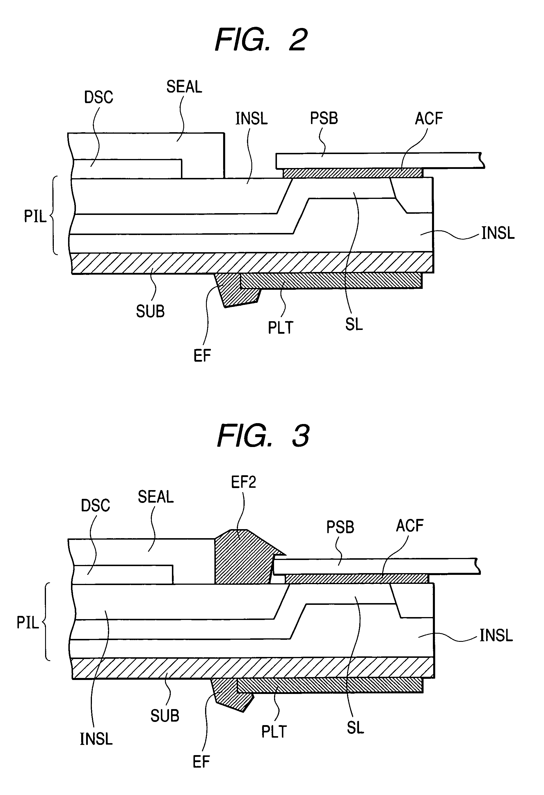
[0056]FIG. 2 is a cross-sectional view similar to that of FIG. 1(c), illustrating another example of a terminal portion of the organic EL display device in accordance with the present invention. This example is different from that illustrated in FIG. 1(c), in that the terminal portion employing the reinforcing plate member PLT having the configuration illustrated in FIG. 1(c) has the reinforcing agent EF attached at a periphery of the reinforcing plate member PLT. The reinforcing agent EF is made of epoxy resin, for example. The reinforcing agent EF is provided to prevent the possibility that peeling-off starts easily at an interface between the comparatively easily bendable flexible substrate SUB and the comparatively less-bendable reinforcing plate member PLT from the periphery of the reinforcing plate member PLT when the organic EL display device is bent. Therefore it is desirable to provide the reinforcing agents EF at three sides of the rectangular reinforcing plate member PLT ...

example 3

[0057]FIG. 3 is a cross-sectional view similar to that of FIG. 2, illustrating another example of a terminal portion of the organic EL display device in accordance with the present invention. This example is different from that illustrated in FIG. 2, in that the reinforcements between the flexible wiring board PSB and the laminate PIL, and between the flexible wiring board PSB and the sealing agent layer SEAL are provided in addition to the reinforcement between the reinforcing plate member PLT and the flexible sustrate SUB. That is to say, since the reinforcing plate member PLT is provided to prevent peeling-off of the flexible wiring board PSB, the expedient for prevention of peeling-off of the flexible wiring board PSB itself.

[0058]In the region where the flexible wiring boards PSB are coupled to the terminals TM, it is desirable to provide spacings between adjacent ones of the flexible wiring boards PSB, and between the flexible wiring boards PSB and the sealing agent layer SEAL...


PUM


Abstract

A flexible display device includes: a flexible substrate which constitutes at least part of an envelope of the flexible display device; a plurality of pixels disposed on the flexible substrate; a group of terminals which is formed at a first portion on one surface of the flexible substrate and supplies signals to the plurality of pixels; and a reinforcing member attached to at least a second portion on another surface of the flexible substrate which faces the first portion across a thickness of the flexible substrate.

Description

CLAIM OF PRIORITY[0001]The present application claims priority from Japanese application serial no. 2003-357882, filed on Oct. 17, 2003, the content of which is hereby incorporated by reference into this application.BACKGROUND OF THE INVENTION[0002]The present invention relates to a display device, and in particular to a display device having a flexible body.[0003]For example, a display device such as an organic EL (electroluminescent) display device has a plurality of gate signal lines extending in an x direction and arranged in a y direction on one surface of a substrate, a plurality of drain signal lines extending in the y direction and arranged in the x direction on the surface, and a plurality of pixel areas each surrounded by two adjacent ones of the gate signal lines and two adjacent ones of the drain signal lines, and each of the pixel areas is provided at least with a thin film transistor which is turned on by a scanning signal from a corresponding one of the gate signal li...

Claims


Application Information

Patent Timeline
Patent Type & Authority Patents(United States)
IPC IPC(8): H01R12/16H05B33/06G09F9/00G09G5/00H01L27/32H01L51/50H01L51/52H05B33/12H05B33/14H05B44/00H05K1/03H05K1/11
CPCG09G3/3233H01L51/52G09G3/3208G09G2300/0819G09G2300/0852G09G2300/0861G09G2320/043H01L27/3244H01L27/3297H01L2227/326H01L2251/5338H10K59/12H10K59/131H10K50/80H10K71/80H10K59/1201H10K2102/311
Inventor OCHIAI, TAKAHIROTANAKA, MASAHIROKANEKO, TOSHIKITAKASAKI, YUKIO
Owner SAMSUNG DISPLAY CO LTD
Why Eureka
Try Eureka