Microneedle Cartridge and Nosecone Assembly

Active Publication Date: 2016-06-23
ESTHETIC MEDICAL INC
View PDF20 Cites 5 Cited by
  • Summary
  • Abstract
  • Description
  • Claims
  • Application Information

AI Technical Summary

Benefits of technology

[0020]Based on the health risks posed to patients by virtue of possible exposure to blood borne pathogens trapped inside the motorized microneedling device and then potentially transmitted to the next patient, it is apparent that current motorized microneedling devices are not capable of preventing fluids from exiting the needle cartridge and entering the device. In order to prevent this, a new cartridge and nose cone assembly system is presented. Three features are combined into a microneedling cartridge interface that prevents the transmission of any fluid from microneedle cartridge into the motorized microneedling device as well as affording the ability to remove and autoclave sterilize the portion of the motorized microneedling device in contact with the microneedle cartridge. Additionally, a polymer reciprocal piston rod affords the ability to provide an adequate connection to the microneedle cartridge receiver while also allowing the reciprocal piston rod to be replaced in the event of damage or wear. The microneedle cartridge apparatus is constructed with two internal baffle cylinders and two absorbent gaskets that prevent any liquid from traveling from the gap between the outer cartridge wall and the inner microneedle array block, through the cartridge and into the motorized microneedling device via the gap between the outer cartridge connection to the motorized device and the central rod affixing the microneedling array. These absorbent gaskets prevent capillary action from facilitating the travel of liquid through the microneedle cartridge and are treated with an antimicrobial agent to marginalize any pathogen coming into contact with the gaskets. Currently, there are no other microneedle cartridges incorporating the use of absorbent material to trap liquids. One inner concentric cylinder slides inside a tightly machined gap between the outer cylinder allowing the central rod with the microneedle array attached to move freely through the outer cartridge connection housing while simultaneously preventing liquids from traversing the gap between them as they are arranged with the height of the smaller central cylinder being greater than the distance traveled outwards into the skin by the central rod attached to the microneedle array. In this way the path through the microneedle cartridge is comprised of two 180 degree turns with absorbent material gaskets at each turn to absorb any liquid that could possibly travel this path. The microneedle cartridge itself is attached to the nose cone of the motorized microneedling device by means of male to female threads. As the microneedle cartridge was designed to prevent fluids from being able to enter the motorized microneedling device, this microneedle cartridge is able to safely utilize a stiff metal return spring maximizing the depth the microneedle array can efficiently enter and withdraw from the skin without tearing it or damaging the electric motor. In order to provide another backup system to further prevent liquids from

Problems solved by technology

Based on the health risks posed to patients by virtue of possible exposure to blood borne pathogens trapped inside the motorized microneedling device and then potentially transmitted to the next patient, it is apparent that current moto

Method used


Image

  • Microneedle Cartridge and Nosecone Assembly
  • Microneedle Cartridge and Nosecone Assembly
  • Microneedle Cartridge and Nosecone Assembly

Examples


Embodiment Construction

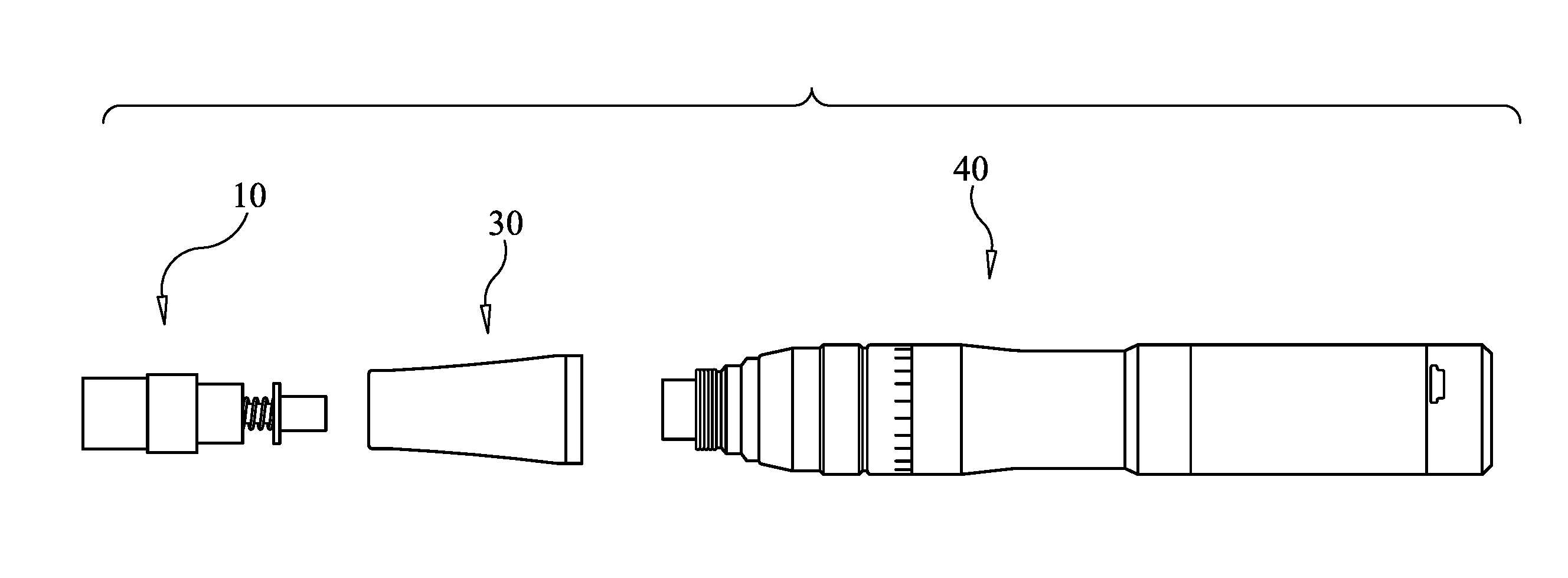
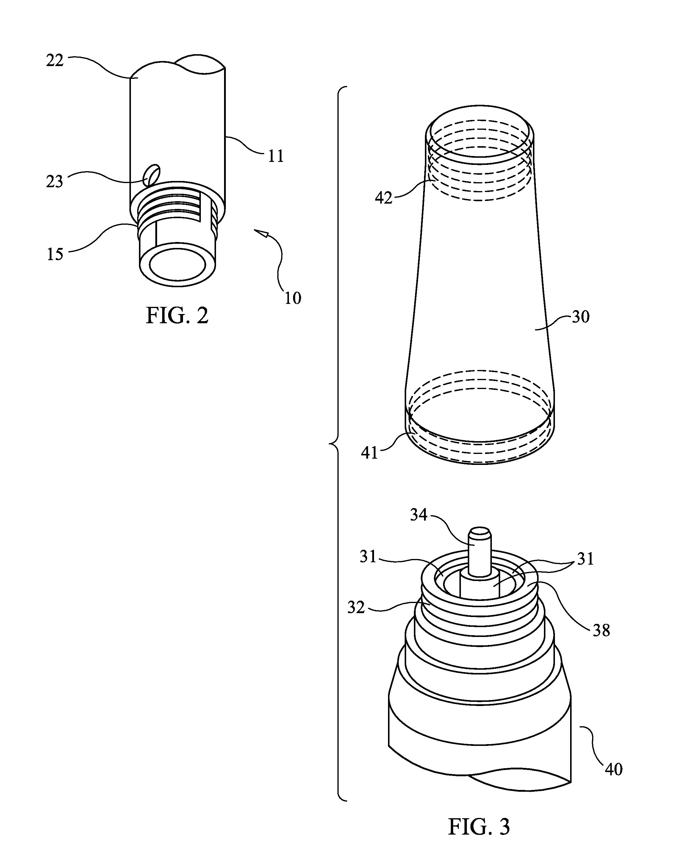
[0030]FIG. 6 illustrates the general configuration of a microneedling pen or microneedling device adapted to employ the present invention. Microneedling device body 40 contains a power source, an electric motor moving a high speed reciprocating piston, and speed and depth controls. Microneedling cartridge 10 comprises an embodiment of the present invention. Nosecone 30 joins the device body 40 and the cartridge 10.

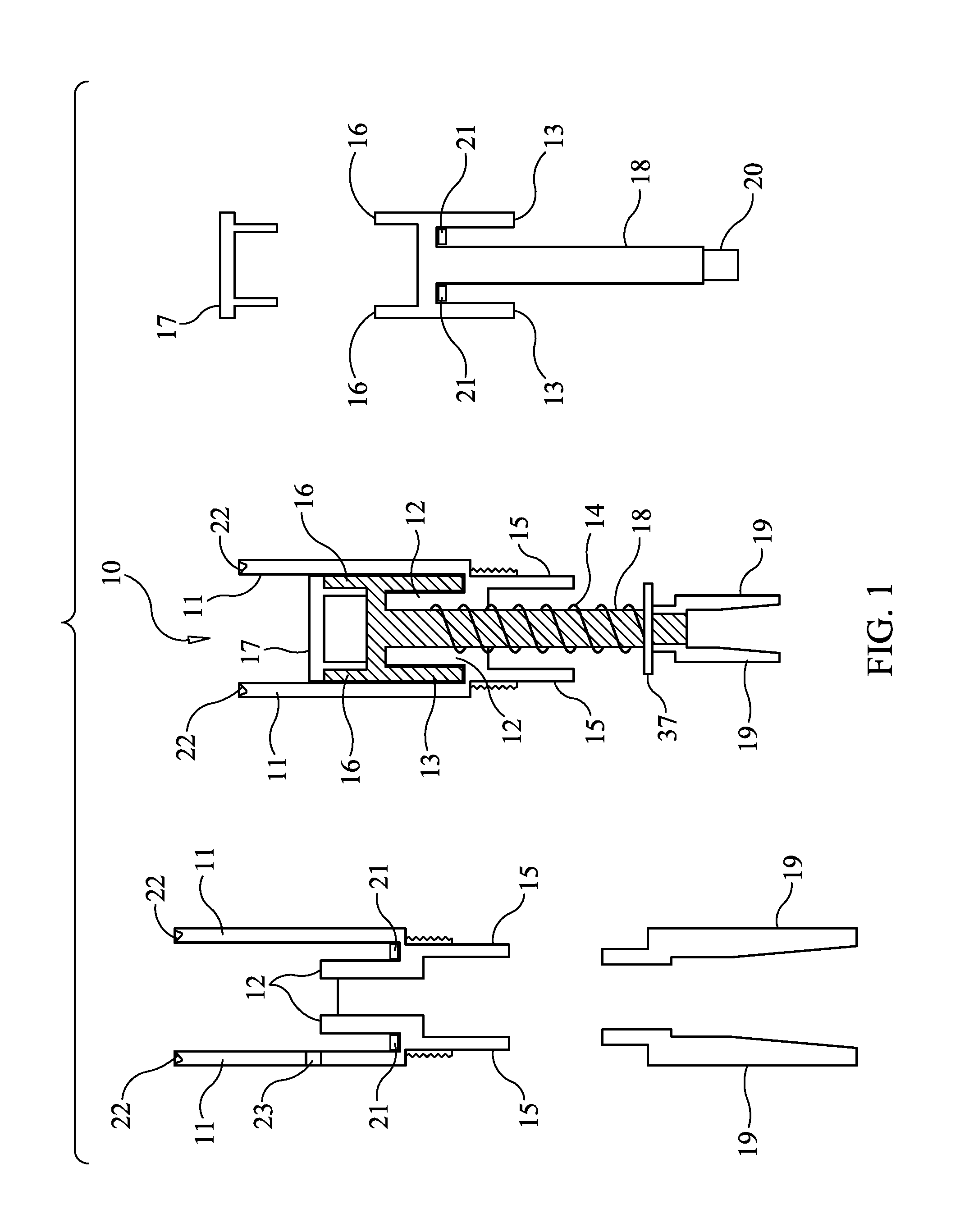
[0031]FIG. 1 is a schematic diagram illustrating the components and assembly of the microneedle cartridge apparatus 10 designed to prevent the transmission of bodily fluids in accordance with one embodiment of the present invention. The central figure shows the cartridge apparatus, with some of the components broken out and repeated on the left and right figures. Microneedle cartridge apparatus 10 includes outer cartridge cylinder 11, which provides support and isolation for internal components. Attached to, and contiguous with outer cartridge cylinder 11 is inner baffle c...


PUM


Abstract

A microneedle cartridge is provided comprising a pair of concentric cylinders wherein an inner cylinder supports a microneedle array block and moves up and down an inside cylinder, driven by a central rod which connects the microneedle array to a drive motor. An inner baffle cylinder fits inside the inner cylinder and surrounds the central rod, isolating the microneedle array from the internal cavity of the machine. Fabric gaskets treated with antimicrobial solution are placed at the locations where the inner baffle cylinder meets the inner cylinder and where the inner cylinder meets the outer cylinder. A piston rod cradle at the bottom of the cartridge engages a cup-shaped polymer reciprocating piston rod that interacts with the device motor through a connecting metal piston. A removable, autoclavable metal nosecone covers the cartridge assembly.

Description

CROSS REFERENCE TO RELATED APPLICATIONS[0001]This application claims the benefit of U.S. provisional patent application 62 / 094,965, filed Dec. 20, 2014.TECHNICAL FIELD OF THE INVENTION[0002]The present device components relate in general to a skin treatment protocol and, more particularly, to an apparatus, a system, and a method to deliver beneficial molecules in order to enhance the appearance of the skin while, simultaneously, prohibiting any liquid, bodily fluid, or topical product from entering into the apparatus.BACKGROUND OF THE INVENTION[0003]In modern society, much importance has been placed on physical appearance. The relative condition of a person's skin often implies health, youth, and beauty. Dermatological conditions such as acne scarring, stretch marks, surgical scars, melasma, and other conditions detract from the appearance of the skin. There has been much attention and research devoted to beautifying the skin.[0004]The skin comprises the largest organ in the body an...

Claims


Application Information

Patent Timeline
IPC IPC(8): A61M37/00
CPCA61M2037/0007A61M37/0015A61M2037/0023
Inventor GROOP, KRISTINGROOP, LAWRENCE G.
Owner ESTHETIC MEDICAL INC
Why Eureka
Try Eureka