Diffuser insert for coal fired burners

a technology of diffuser insert and coal burner, which is applied in the direction of gas current separation, combustion types, lighting and heating apparatus, etc., can solve the problems of loss on ignition, distribution problems tend to occur, and unbalanced stream, and achieve the effect of simplifying the installation tasks

Inactive Publication Date: 2005-01-11
WARK RICKEY E
View PDF34 Cites 13 Cited by
  • Summary
  • Abstract
  • Description
  • Claims
  • Application Information

AI Technical Summary

Benefits of technology

The present invention is a multi-directional, multi-layer diffuser structure adapted to be inserted as a unit into a pipe, in particular in the short run of pipe between an elbow

Problems solved by technology

Each type of mill presents its own problems with respect to the goal of supplying an even, balanced flow of coal fines through multiple pipes to multiple burners in the combustion chamber.
In suction mills, for example, the exhauster fan tends to throw coal in an unbalanced stream, with heavier particles settling out to one side of the flow through the pipe and lighter fines on the other.
In pressurized mills without exhauster fans, distribution problems tend to occur as a result of the varying lengths of discharge pipe leading from the top of the classifier to the various burners around the combustion chamber.
Rich/lean imbalances among the various burners in the combustion chamber produce the usual problems: loss on ignition (LOI) contamination of the ash byproduct; NOX formation; fireball distortion and waterwall erosion; and others known to those skilled in the art.
The problem with clean air flow testing is that, having balanced air flow in a theoretical test, the introduction of coal fines produces fundamentally different results than the air-only testing would indicate, and the orifice plates worsen distribution problems among and within the pipes.
As a result, further efforts have attempted on-line adjustable orificing with coal flow present, with similarly disappointing results.
It has been found, however, that the use of dynamic classifiers still results in significant differenc

Method used


Image

  • Diffuser insert for coal fired burners
  • Diffuser insert for coal fired burners
  • Diffuser insert for coal fired burners

Examples


Embodiment Construction

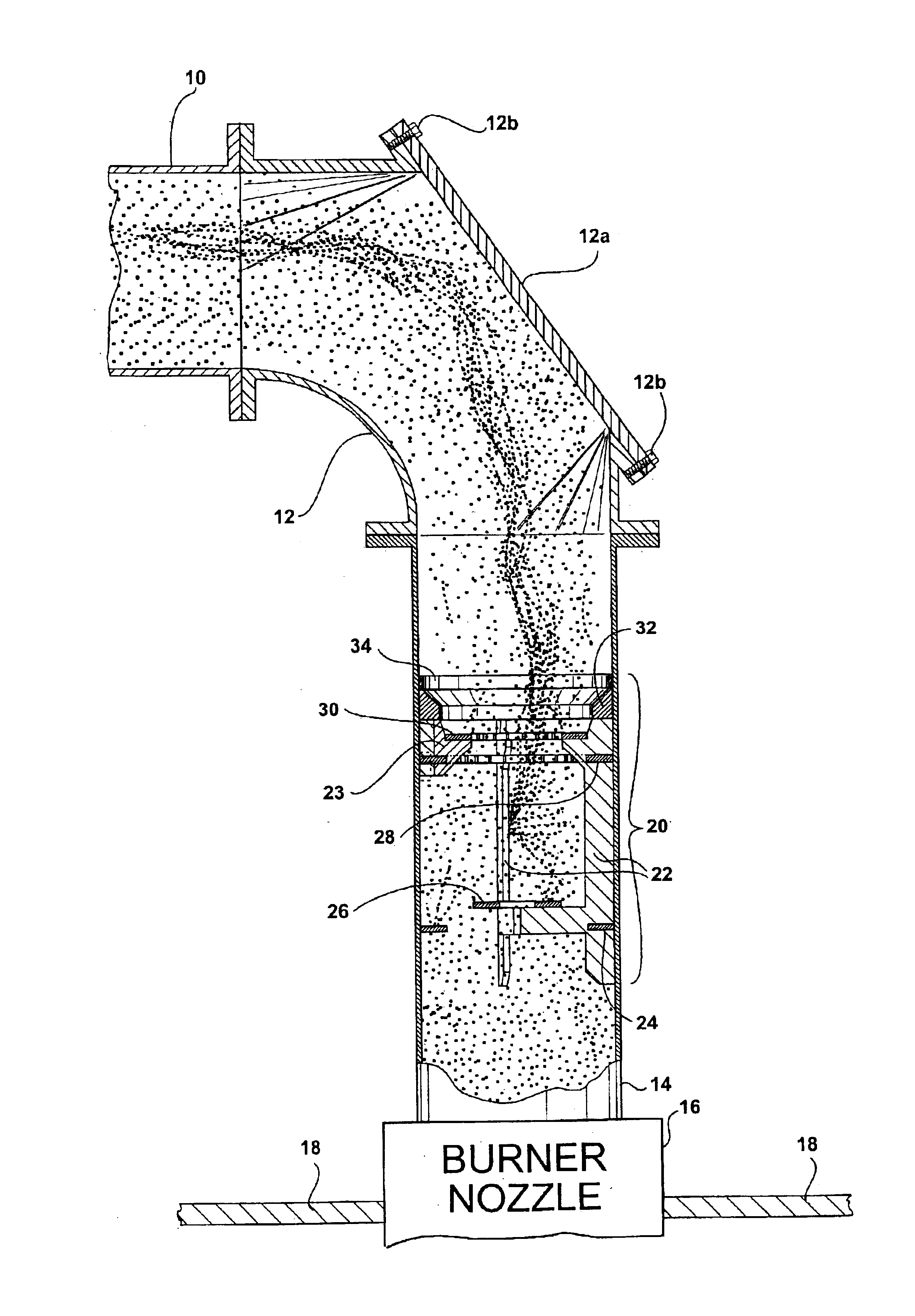
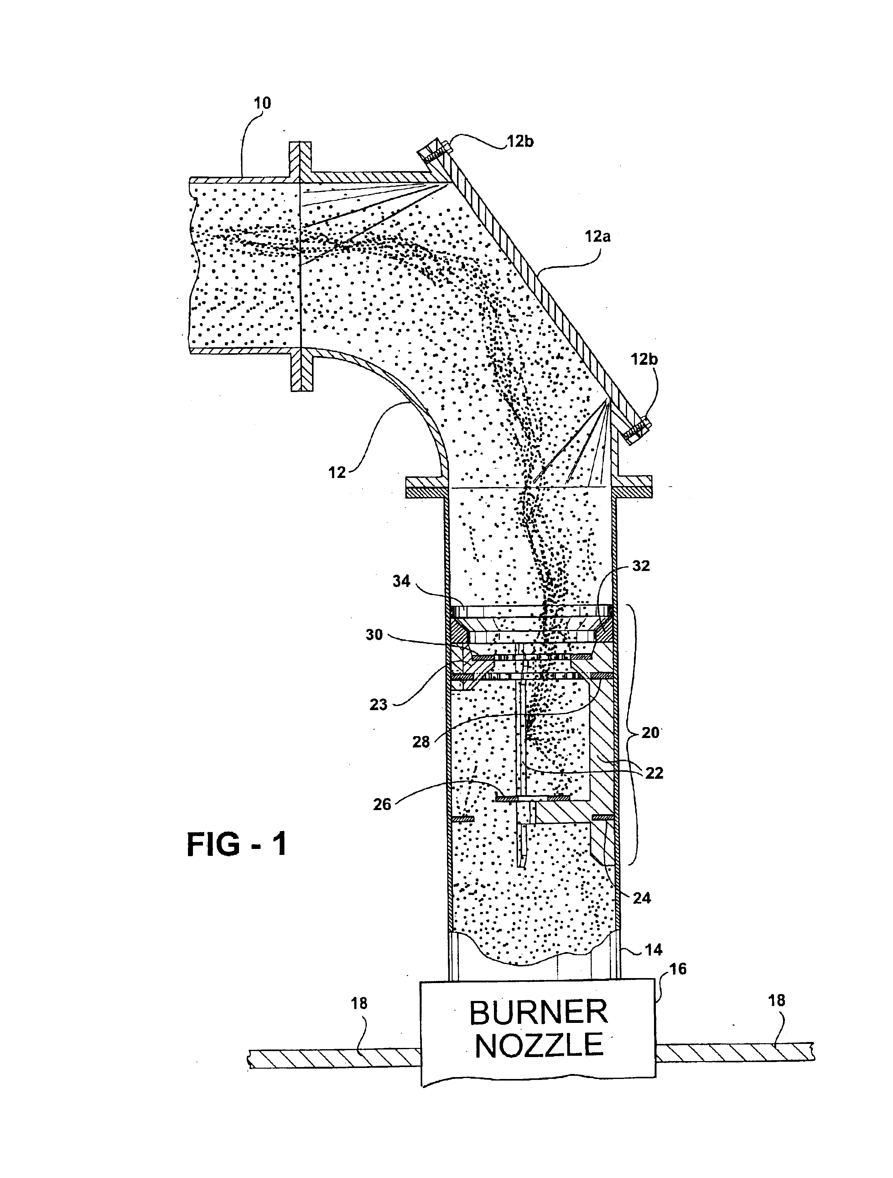
Referring first to FIG. 1, a pipe 10 delivers a flow of pulverized coal and air from a source of pulverized coal such as a pulverizer / classifier (not shown) to a burner nozzle 16 mounted in the wall of a combustion chamber 18. The end of pipe 10 is re-routed into alignment with burner nozzle 16 in common fashion, using an elbow pipe section 12 and a short length of connector pipe 14 between the elbow and the burner nozzle. This general arrangement of piped coal supply from a classifier to a combustion chamber is well known, and the specifics of burner nozzle, combustion chamber, piping, and classifier can vary as is known to those skilled in the art.

As noted above, the typical combustion chamber is supplied with many burner nozzles, for example from two to twelve. Attempts are usually made upstream, sometimes beginning at the classifier itself, to ensure that the flow of pulverized coal is evenly balanced among the burners. Once the coal reaches the burner nozzles, the nozzles thems...


PUM


Abstract

A diffuser for a pulverized coal delivery pipe near an elbow connection to a burner nozzle. A diffuser structure is located in the pipe adjacent the elbow outlet, with both radial and axial diffuser elements for diffusing radial and axial components of coal concentrations between the elbow and the nozzle. In a preferred form, the elbow is formed with an access hatch aligned with the pipe at the elbow outlet, and the diffuser structure is formed as a drop-in insert that can be installed and accessed through the hatch. The diffuser has a venturi inlet that produces an initial diffusion effect with minimal pressure drop before the coal flow reaches the radial and axial collision-style diffuser elements.

Description

FIELD OF THE INVENTIONThe present invention is in the field of diffuser structure used in a coal classifying and delivery flow path between a pulverizer and a combustion chamber in a coal-fired power plant.BACKGROUND OF THE INVENTIONIn the field of coal pulverizing mills there are generally two types of mills, characterized by the manner in which the pulverized coal is delivered from the mills to a combustion chamber: “suction” mills using exhauster fans to pull the pulverized coal fines from the mill through discharge pipes; and, fanless “pressurized” mills that typically entrain the pulverized coal fines in a stream of pressurized air originating at the mill.Each type of mill presents its own problems with respect to the goal of supplying an even, balanced flow of coal fines through multiple pipes to multiple burners in the combustion chamber. In suction mills, for example, the exhauster fan tends to throw coal in an unbalanced stream, with heavier particles settling out to one si...

Claims


Application Information

Patent Timeline
IPC IPC(8): B02C23/00B02C23/16B04C5/13B04C5/00F23K1/00B02C15/00
CPCB02C23/16B04C5/13F23K3/02F23K1/00B02C2015/002F23K2203/105F23K2201/1006
Inventor WARK, RICKEY E.
Owner WARK RICKEY E
Why Eureka
Try Eureka