Friction-type continuously variable transmission

a transmission type and continuously variable technology, applied in the direction of friction gearings, belts/chains/gearings, friction gearings, etc., can solve the problems of difficulty in reducing production costs, large number of parts, and increased weight, and achieve the effect of reducing the number of parts

Active Publication Date: 2018-12-04
NIDEC SHIMPO CORP
View PDF19 Cites 0 Cited by
  • Summary
  • Abstract
  • Description
  • Claims
  • Application Information

AI Technical Summary

Benefits of technology

[0007]In view of the above-described circumstances, the present invention has been conceived to achieve improved transmission performance and a reduced number of parts of a friction-type continuously variable transmission.
[0009]According to one preferred embodiment of the present invention, a friction-type continuously variable transmission is able to achieve a reduced number of parts, and is capable of continuously varying the speed ratio without adopting a complicated mechanism.

Problems solved by technology

Such a known continuously variable transmission as described above has a complicated transmission mechanism, and therefore has problems in a large number of parts and an increased weight, and additionally in difficulty in reducing a production cost.

Method used


Image

  • Friction-type continuously variable transmission
  • Friction-type continuously variable transmission
  • Friction-type continuously variable transmission

Examples


Embodiment Construction

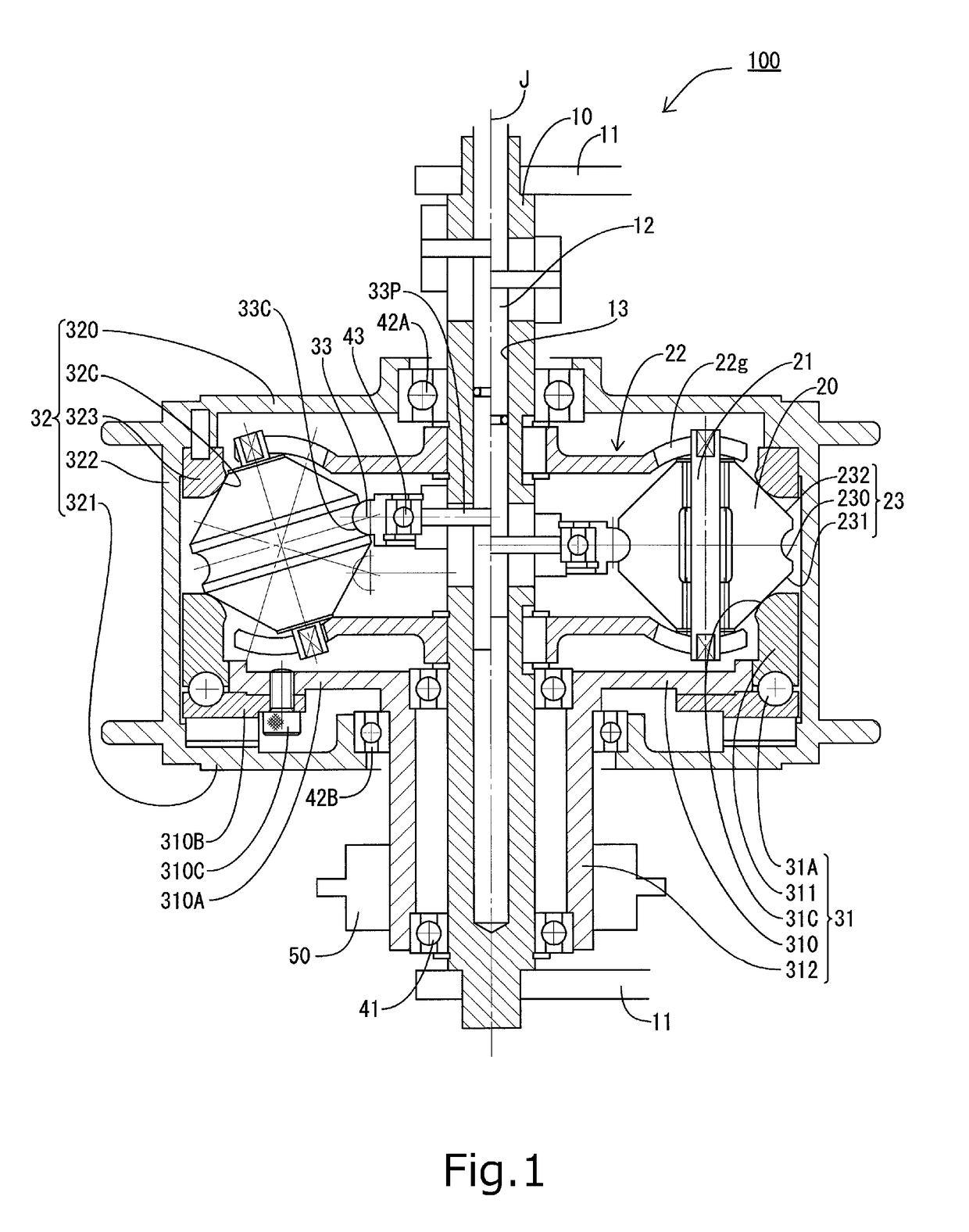
[0021]Hereinafter, preferred embodiments of the present invention will be described with reference to the accompanying drawings. For the sake of convenience in description, a direction parallel to a principal axis J of a continuously variable transmission is herein referred to as a vertical direction. However, this definition of the vertical direction should not be construed to restrict in any way the orientation of a continuously variable transmission according to any preferred embodiment of the present invention when in use. In addition, the direction parallel to the principal axis J is referred to simply by the term “axial direction”, “axial”, or “axially”, radial directions centered on the principal axis J are each referred to simply by the term “radial direction”, “radial”, or “radially”, and a circumferential direction about the principal axis J is referred to simply by the term “circumferential direction”, “circumferential”, or “circumferentially”.

[0022]FIG. 1 is a diagram il...


PUM


Abstract

A friction-type continuously variable transmission includes first to third rolling elements of which are annular and is centered on a principal axis, planetary rollers arranged in a circumferential direction about the principal axis, support pins arranged to rotatably support the planetary rollers, and a planetary roller support portion arranged to support each support pin such that the support pin is capable of inclining in a section including the principal axis. Each planetary roller includes a recessed portion in the shape of a circular ring in an outer circumference thereof centered on the support pin. The first rolling element is arranged to make contact with a rolling contact surface of the planetary roller from one side in a radial direction axially below the recessed portion. The first rolling element is arranged to make contact with the rolling contact surface of the planetary roller from the one side in the radial direction axially above the recessed portion. The third rolling element is arranged to make contact with the recessed portion of the planetary roller from an opposite side in the radial direction, and is supported to be capable of moving in a vertical direction relative to the planetary roller support portion.

Description

BACKGROUND OF THE INVENTION[0001]1. Field of the Invention[0002]The present invention relates to a friction-type continuously variable transmission.[0003]2. Description of the Related Art[0004]Continuously variable transmissions including a plurality of planetary rollers have been known (for example, JP-A 2011-231929). In a continuously variable transmission described in JP-A 2011-231929, a plurality of balls are distributed on a plane perpendicular to a shaft. Each ball makes contact with an input disk on one side, and makes contact with an output disk on an opposite side, and a torque is transferred from the input disk to the output disk (134) through the balls.[0005]Each ball includes a ball shaft capable of inclination, and the speed ratio between the input disk and the output disk can be adjusted by varying the inclination angle of the ball shaft with respect to the shaft. The balls are supported by a pair of arms such that each ball is capable of inclination. The pair of arms,...

Claims


Application Information

Patent Timeline
Patent Type & Authority Patents(United States)
IPC IPC(8): F16H13/08F16H15/52F16H15/04F16H15/50
CPCF16H15/52F16H15/04F16H13/08F16H15/506
Inventor OKAMURA, KIKUOINOUE, HITOSHIDEGUCHI, NORIO
Owner NIDEC SHIMPO CORP
Why Eureka
Try Eureka