
Cut resistant glove, and manufacturing method of cut resistant glove

a manufacturing method and glove technology, applied in the field of cut resistant gloves and manufacturing methods of cut resistant gloves, can solve the problems of difficult to ensure the texture and/or fit of the glove, the effect of the additional yarn by the plating knitting becomes inferior, and the conventional ground yarn becomes less flexible, so as to achieve the effect of superior texture and fi

Active Publication Date: 2019-01-01
SHOWA GLOVE
View PDF25 Cites 4 Cited by
  • Summary
  • Abstract
  • Description
  • Claims
  • Application Information

AI Technical Summary

Benefits of technology

[0021]As explained in the foregoing, the cut resistant glove of the present invention has stretchability, and is superior in the texture and fit, while a string made of a metal or glass fiber is prevented from sticking out irrespective of the gauge number.

Problems solved by technology

Thus, the effect of the additional yarn by the plating knitting becomes inferior, and for example, the ground yarn is likely to be exposed from the gap of the additional yarns, whereby it may be difficult to ensure the texture and / or the fit of the glove.
In addition, due to having a structure in which the cover yarn squeezes the core material, the conventional ground yarn becomes less flexible, thereby being more likely to give hard feel on touch.
Accordingly, even in the case of gloves composed of smaller stitches of at least 13 gauges for which higher flexibility is expected, as compared with gloves composed of larger stitches of less than 13 gauges (for example, 10 gauges), the flexibility may be insufficient when the conventional ground yarn is used.

Method used


Image

  • Cut resistant glove, and manufacturing method of cut resistant glove
  • Cut resistant glove, and manufacturing method of cut resistant glove
  • Cut resistant glove, and manufacturing method of cut resistant glove

Examples


example 1

[0091]Production of Ground Yarn

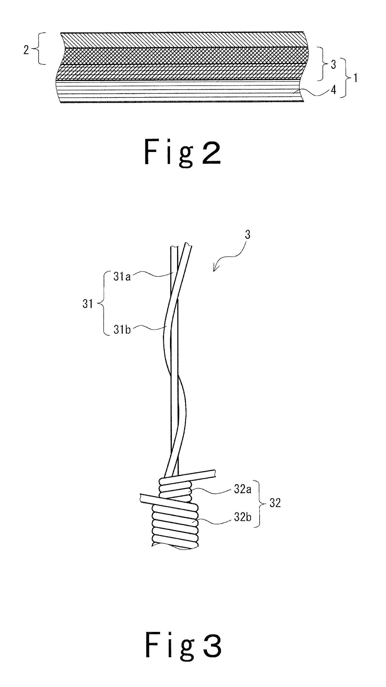
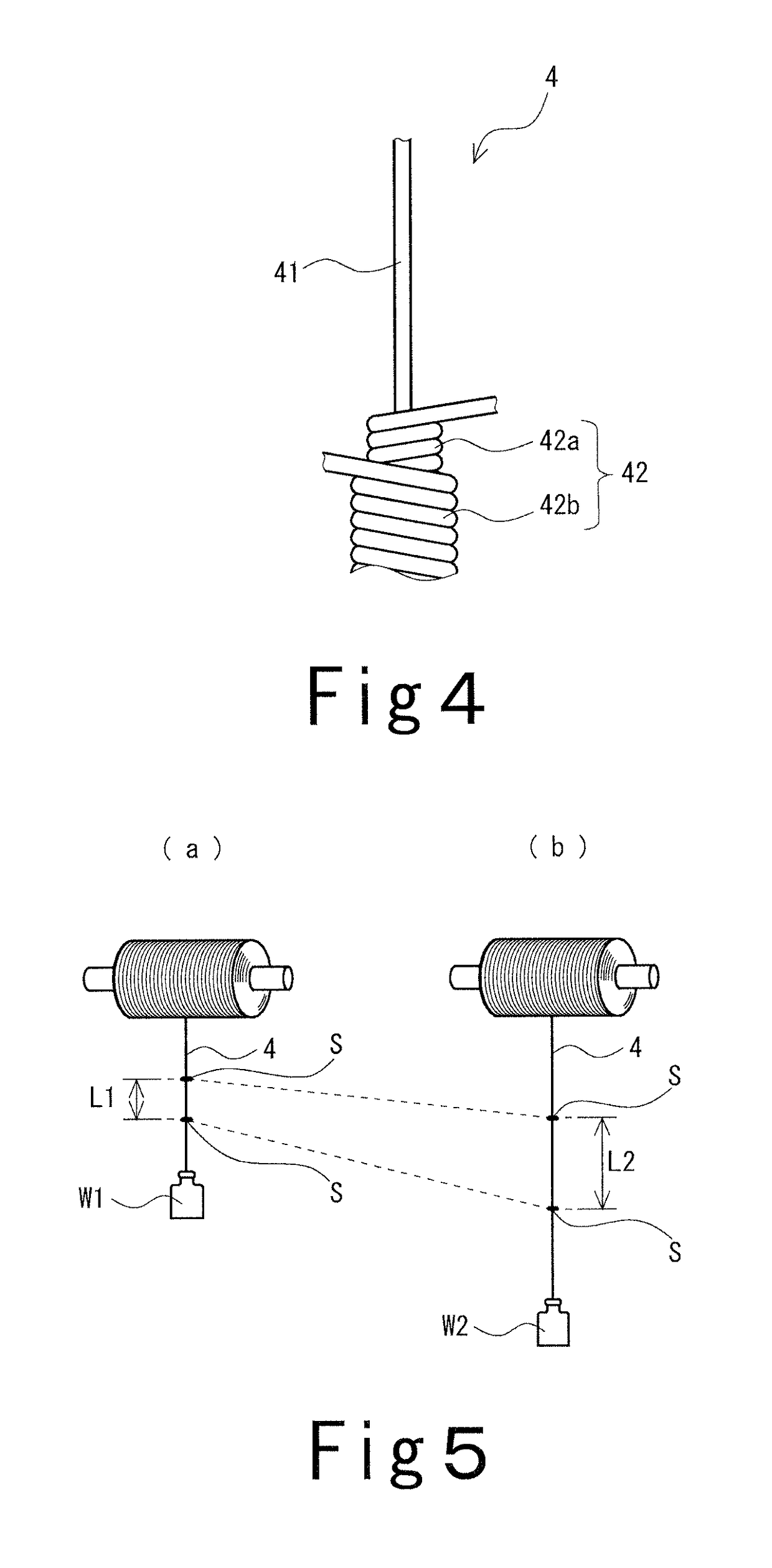
[0092]A straight polyester filament yarn (number of the filament: 24; 78 dtex) not subjected to a false twisting processing was gently wound around one stainless wire (manufactured by Nippon Seisen Co., Ltd.) having a diameter of 30 μm, at a number of winding of 30 times / meter (TPM) so as to lie along the stainless wire, and thereon by using two polyester textured yarns (number of the filament: 36; 83 dtex), winding by S twisting and Z twisting at a number of winding of 700 times / m was each executed to produce a ground yarn.

[0093]Production of Additional Yarn

[0094]While taking-up one Spandex of 22 dtex with three-times elongation (draft setting value: 3) , winding of two woolly nylon yarns (number of the filament: 24; 156 dtex in total with two-ply yarn of 78-dtex yarns; by S twisting and Z twisting at a number of winding of 200 times / m was each executed to produce an additional yarn.

[0095]Knitting of Glove

[0096]The ground yarn and the additional yarn ...

example 9

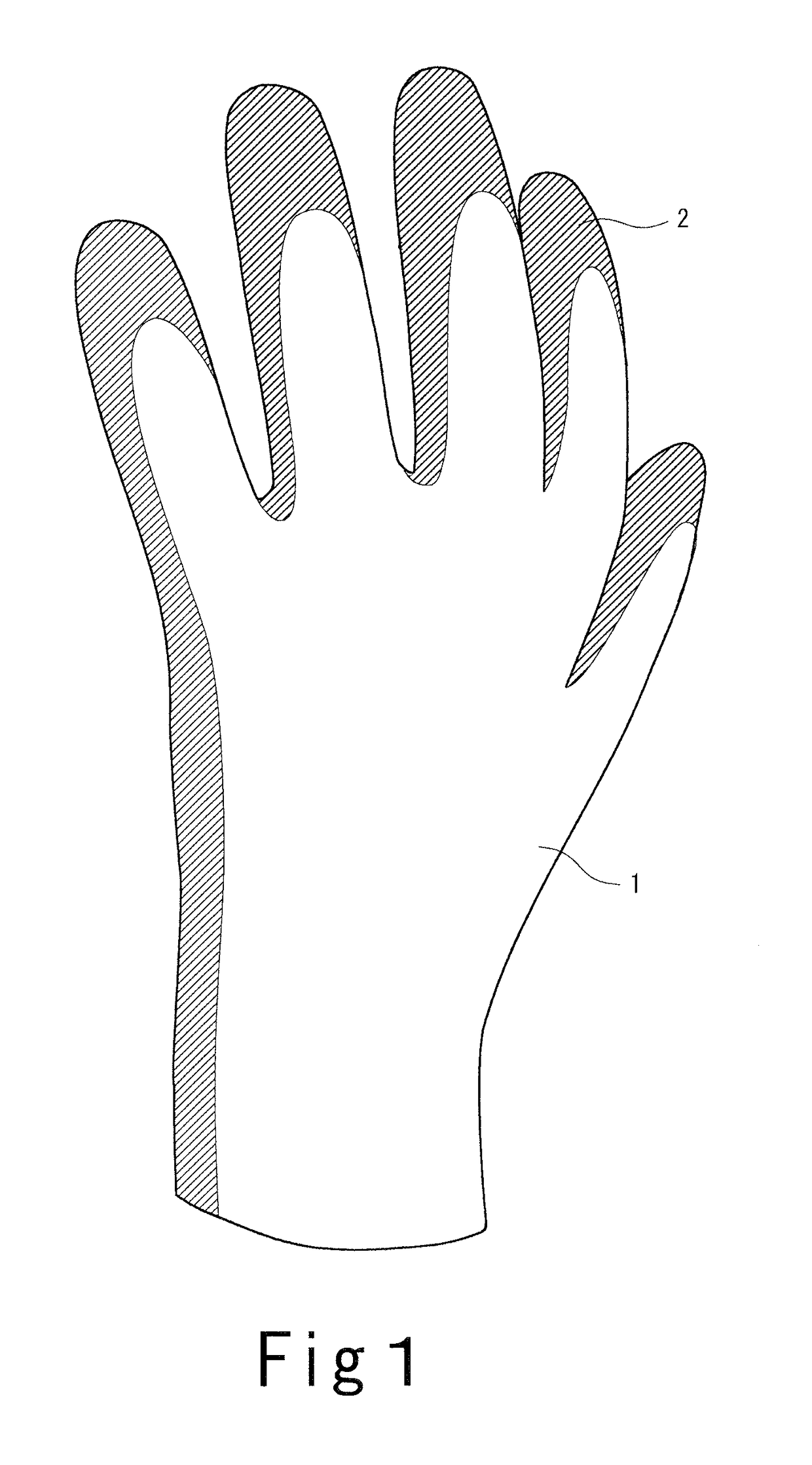
[0101]A cut resistant glove was obtained in a similar manner to Example 1 except that the knitted glove was not reversed in the knitting of the glove of Example 1. It is to be noted that regarding the arrangement of the yarns, the additional yarn is placed on the outer surface side.


PUM

PropertyMeasurementUnit
elongationaaaaaaaaaa
elongation rateaaaaaaaaaa
weightaaaaaaaaaa

Abstract

Provided is a cut resistant glove having stretchability and being superior in the texture and fit while a string made of a metal or glass fiber is prevented from sticking out, irrespective of the gauge number. A cut resistant glove having a glove main body manufactured by plating knitting using a ground yarn and an additional yarn, in which the ground yarn includes a core material, and a cover yarn wound around the core material, the core material having a string made of a metal or glass fiber, and the additional yarn being made of an organic fiber, and in which the ratio of the average thickness of the additional yarn to the average thickness of the ground yarn is no less than 0.9 and no greater than 2.5. The core material preferably further has a support yarn made of an organic fiber arranged along the string.

Description

TECHNICAL FIELD[0001]The present invention relates to a cut resistant glove, and a method for manufacturing a cut resistant glove.BACKGROUND OF THE INVENTION[0002]As cut resistant gloves for use in operations in which a sharp edged tool is used, operations in which glass, metal plate, etc., with a sharp edge is used, and the like, cut resistant gloves knitted using a ground yarn having a string made of a metal or glass fiber as a core material have been known.[0003]In the ground yarn used in such conventional cut resistant gloves proposed, for the purpose of preventing the glove from deterioration of the texture due to the string that sticks out from the surface of the ground yarn, the string and a support yarn made of an organic fiber provided along the string are used as a core material, and a cover yarn is wound around the core material (see Japanese Patent Nos. 4897684 and 5349797). According to the conventional cut resistant glove, sticking out of the string due to cutting is p...

Claims


Application Information

Patent Timeline
Patent Type & Authority Patents(United States)
IPC IPC(8): A41D19/00D04B1/28D02G3/44A41D19/015D02G3/12
CPCA41D19/01505D02G3/12D02G3/442D04B1/28D10B2403/0114D10B2403/0112A41D2500/10A41D2500/54
Inventor TAKATA, TERUYOSHI
Owner SHOWA GLOVE
Learn More