Support structure for electronics having fluid passageway for convective heat transfer

a support structure and fluid passage technology, applied in the direction of support structure mounting, cooling/ventilation/heating modification, printed circuit board receptacles, etc., can solve the problems of limited use of structures, structure may not provide effective cooling, and support structures may be too bulky for some environments

Active Publication Date: 2019-01-08
HONEYWELL INT INC
View PDF35 Cites 71 Cited by
  • Summary
  • Abstract
  • Description
  • Claims
  • Application Information

AI Technical Summary

Problems solved by technology

However, some structures may be of limited use for some situations.
The structure may not provide effective cooling given the number of PCBs, the heat load from the PCBs, the ambient temperature, and other factors.
Also, some support structures may be too bulky for some environments.
For example, the support structure may not be compact enough for use within an aircraft or other vehicle, given the limited amount of available space.
If there are a large number of electronics components to be cooled, the structure may be quite bulky.
Additionally, the support structure and its associated cooling features can add a significant amount of weight to the vehicle, which can negatively impact fuel efficiency of the vehicle and / or other vehicle performance characteristics.

Method used


Image

  • Support structure for electronics having fluid passageway for convective heat transfer
  • Support structure for electronics having fluid passageway for convective heat transfer
  • Support structure for electronics having fluid passageway for convective heat transfer

Examples


Embodiment Construction

[0019]The following detailed description is merely exemplary in nature and is not intended to limit the present disclosure or the application and uses of the present disclosure. Furthermore, there is no intention to be bound by any theory presented in the preceding background or the following detailed description.

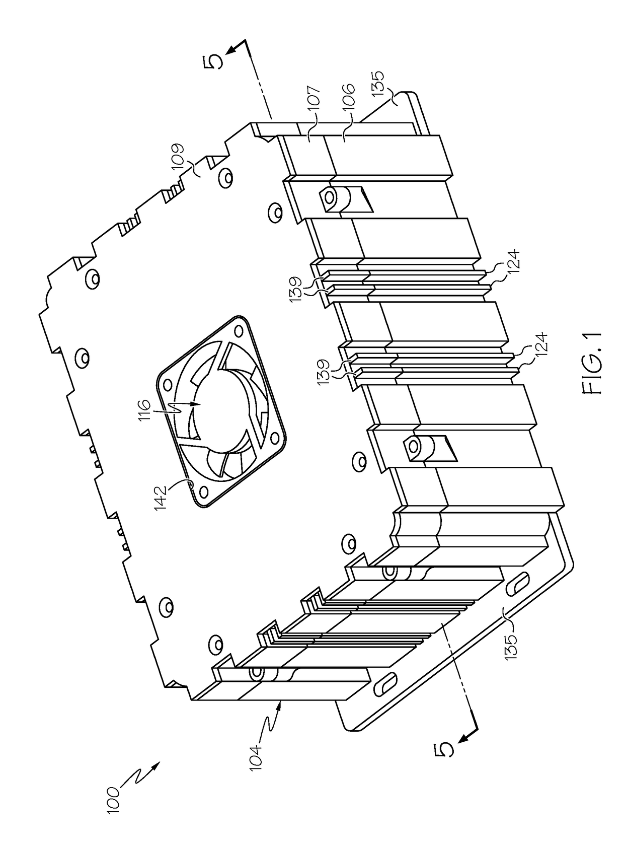
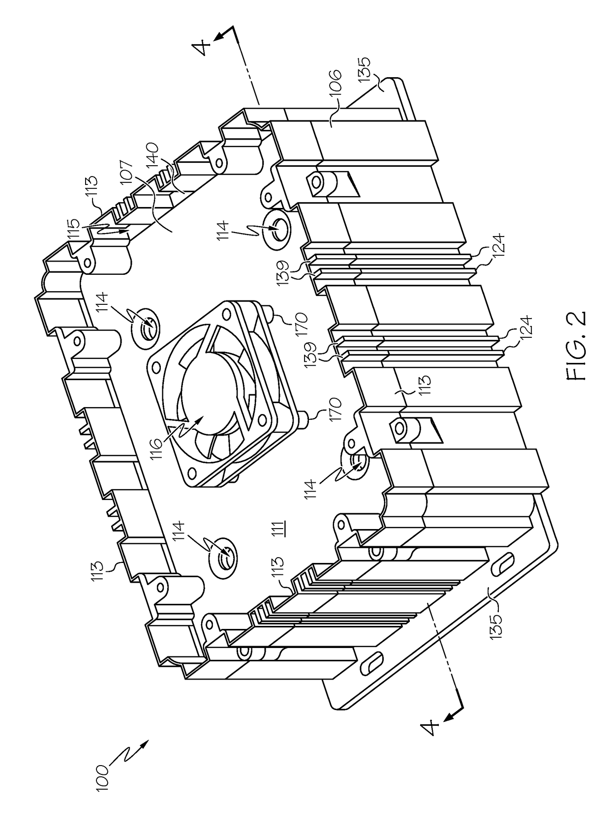
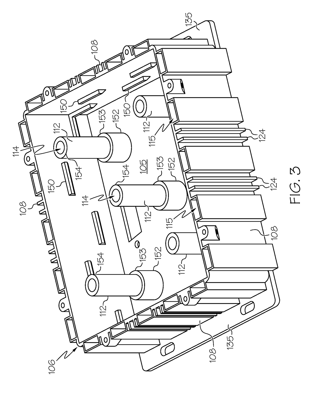
[0020]Example embodiments disclosed herein include a support structure that supports and / or at least partially encloses an electronic component therein. The support structure may include a chassis and a standoff that supports the electronic component with respect to the chassis. At least one fluid passageway may be defined through the standoff. A fluid may flow through the passageway for convectively transferring heat generated by the electronic component away from the support structure. In some embodiments, transverse members may extend transversely across the fluid passageway and may be exposed to the fluid flowing through the passageway. Accordingly, heat in the transver...


PUM


Abstract

A support structure for an electronic component a chassis and a standoff that is attached to the chassis. The standoff is configured to support the electronic component and separate the electronic component at a distance away from the chassis. The standoff is configured to receive heat generated by the electronic component. The standoff includes a fluid passageway. The fluid passageway is configured to allow a cooling fluid to flow therethrough for convective heat transfer from the standoff to the cooling fluid.

Description

TECHNICAL FIELD[0001]The present disclosure generally relates to a support structure for supporting one or more electronic components such as a printed circuit board (PCB) and relates, more particularly, to a support structure for electronic components having one or more fluid passageways for convective heat transfer and convective cooling of the electronics.BACKGROUND[0002]Some devices include a number of electronic components, such as printed circuit boards (PCBs) for operating the device. Typically, the PCB mechanically supports and electrically connects electronic components using conductive tracks, pads, and other features that are etched from conductive material laminated on a non-conductive substrate. The PCB may be supported by a support structure that maintains the PCB in a predetermined position and that maintains an electric connection to other components.[0003]In some cases, the support structure may provide features that cool the PCB and maintain the PCB within a predet...

Claims


Application Information

Patent Timeline
Patent Type & Authority Patents(United States)
IPC IPC(8): H05K7/20H05K7/14
CPCH05K7/20263H05K7/20272H05K7/1427H05K7/20163
Inventor MAHALINGAM, SARAVANANAIK, ABHAYKASAL, YATHIRAJHOTA, RAKESHVRUKSHAVAI, RAJENDRA PRASADKURIAKOSE, MATHEWS LESLIERADHAKRISHNAN, RAVI ANEKAL
Owner HONEYWELL INT INC
Why Eureka
Try Eureka