Eureka AIR delivers breakthrough ideas for toughest innovation challenges, trusted by R&D personnel around the world.

Method for free space optical communication utilizing patterned light and convolutional neural networks

a free space optical communication and neural network technology, applied in the field of optical communication methods and/or apparatuses, can solve the problems of channel crosstalk, limited number of modes, and degradation of signals, and achieve the effect of eliminating the difficult and time-consuming alignment process and avoiding costly optical solutions

Active Publication Date: 2019-01-22
UNITED STATES OF AMERICA
View PDF43 Cites 11 Cited by
  • Summary
  • Abstract
  • Description
  • Claims
  • Application Information

AI Technical Summary

Benefits of technology

[0016]An embodiment of the invention includes a CNN-based demultiplexing method that avoids costly optical solutions by relying only on an intensity image of the unique multiplexing patterns at the receiver side. The natural translation invariance built into such a network topology eliminates the difficult and time consuming alignment process between the optical elements which would be required for traditional demultiplexing techniques.

Problems solved by technology

Due to the complexity of the information that needs to be transmitted and / or the length of time allowed for transmission, it is often necessary to increase the information capacity of the data link.
The parameter, mϵ, is the topological charge or mode number and indicates that there is a theoretically infinite number of modes possible; due to noise, however, this number of modes is limited, in practice.
However, the presence of turbulence causes the mixing of information between adjacent modes, which produces channel crosstalk.
Such channel crosstalk results in the degradation of the signal and a loss of information.
The demultiplexing system is very sensitive to the placement of transforming elements, where a small displacement errors can cause phase errors.
This method does move away from the practice of measuring OAM using optically-based techniques (i.e., holograms, interferometers, etc.) but does not take advantage of the spatial and symmetric information present in the OAM patterned light.

Method used


Image

  • Method for free space optical communication utilizing patterned light and convolutional neural networks
  • Method for free space optical communication utilizing patterned light and convolutional neural networks
  • Method for free space optical communication utilizing patterned light and convolutional neural networks

Examples


Embodiment Construction

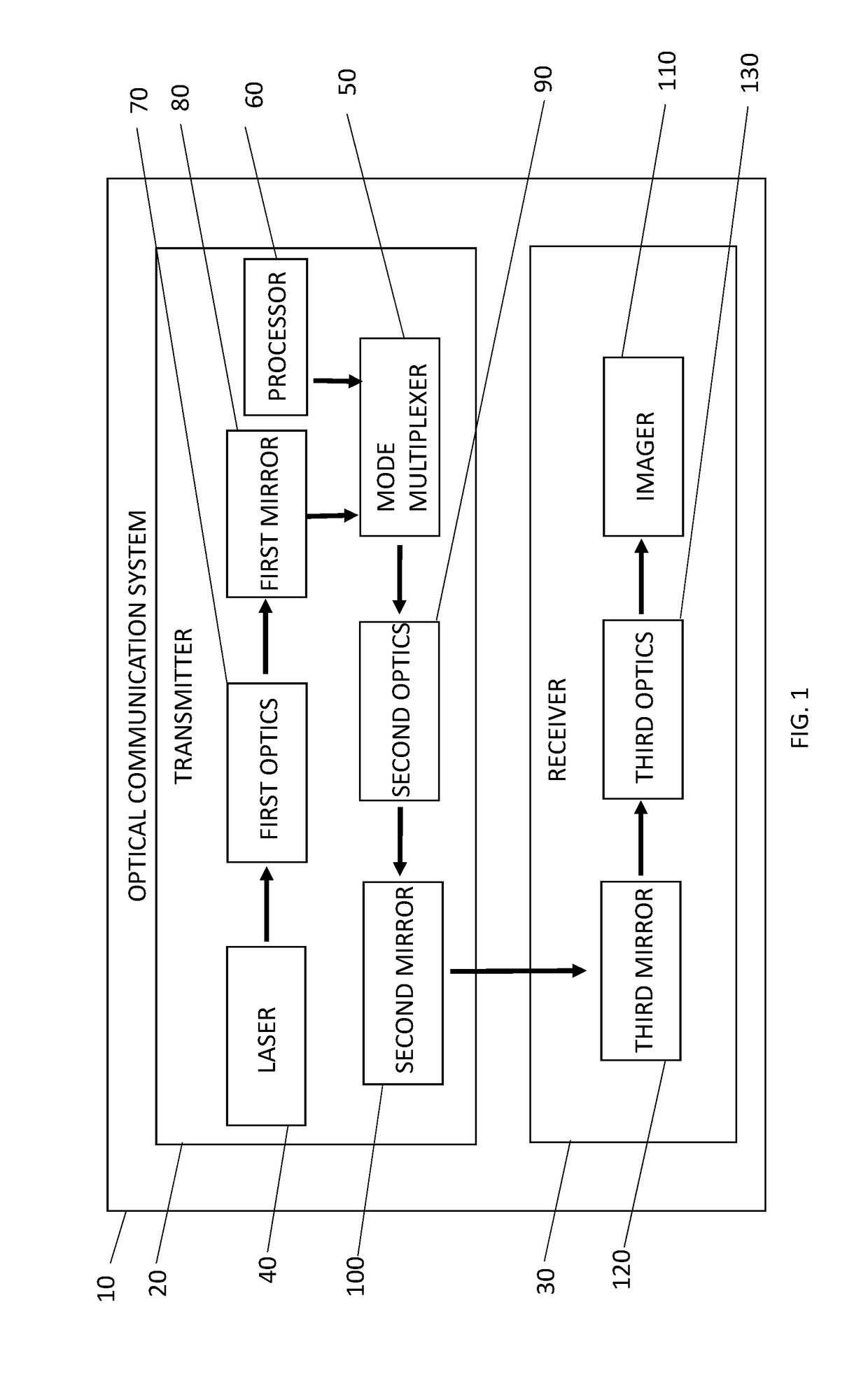
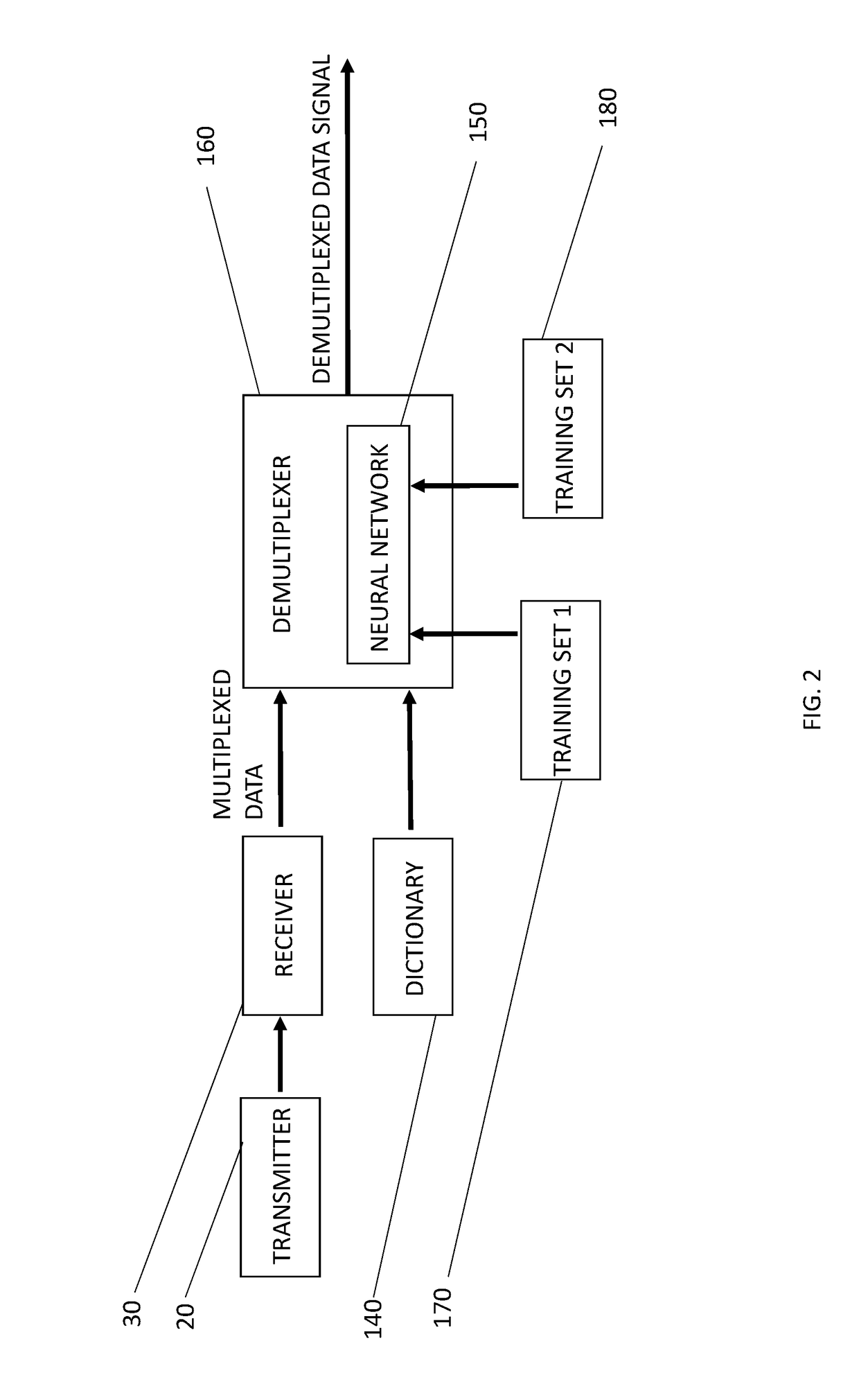
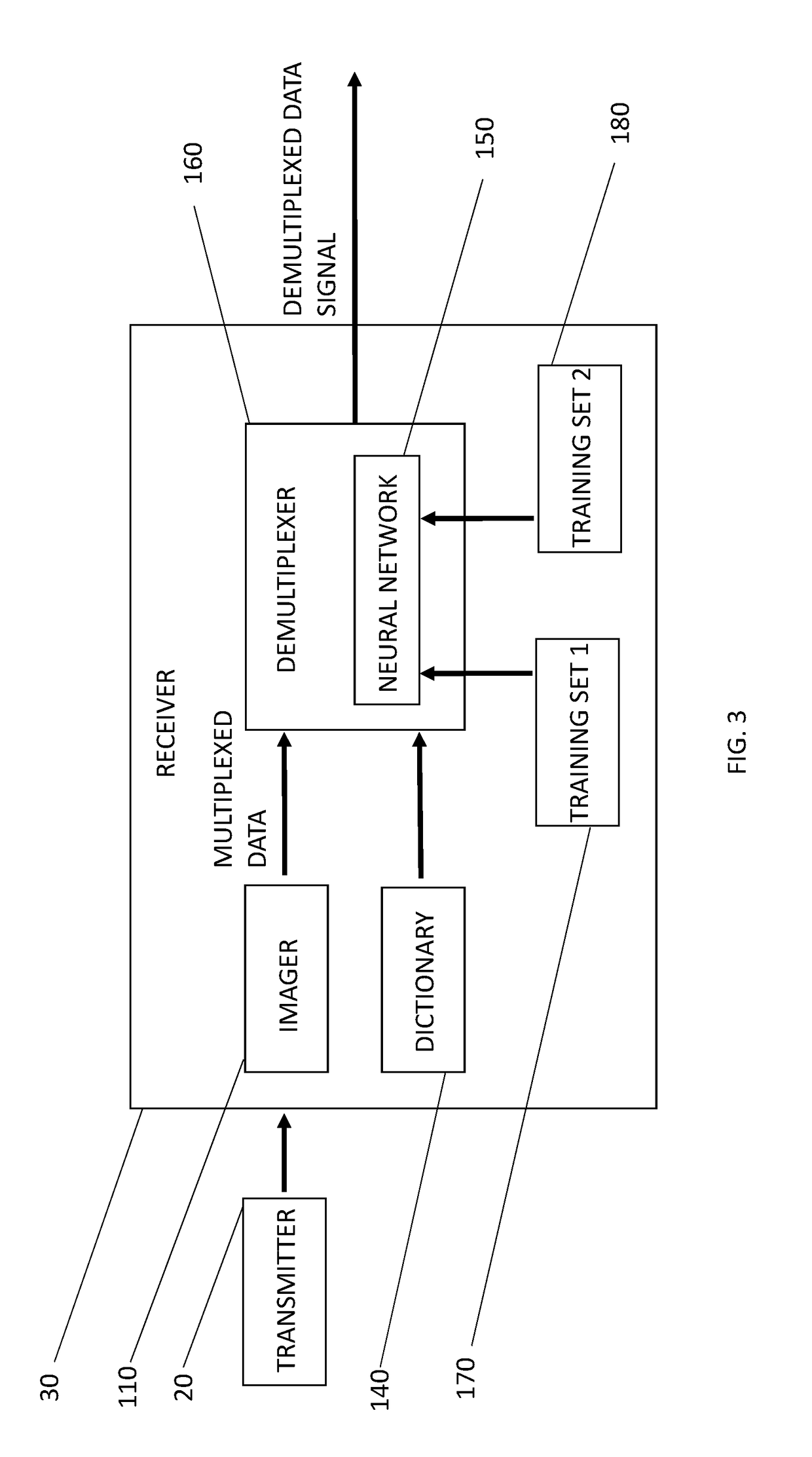
[0021]An embodiment of the invention includes an optical communication system 10, which is described as follows with reference by way of illustration to FIGS. 1-3. As shown by way of example, in FIG. 1, the optical communication system 10 generally includes a standard optical communications transmitter 20 communicating with a standard optical communications receiver 30 over a turbulence-inducing environment. Examples of such environments include a free-space environment and a water environment. One of ordinary skill in the art will readily appreciate that the optical communications transmitter 20 includes a standard free-space optical communications transmitter or a standard underwater optical communications transmitter, depending on the environment through which optical signals are to be transmitted. Likewise, one of ordinary skill in the art will readily appreciate that the optical communications receiver 30 includes a standard free-space optical communications receiver or a stand...


PUM


Abstract

An apparatus includes an optical communications receiver receiving a turbulence-distorted, optical signal. The turbulence-distorted, optical signal includes a plurality of fundamental modes encoded via a combinatorial multiplexings dictionary. The received optical signal includes a plurality of two-dimensional images. Each two-dimensional image of the plurality of two-dimensional images respectively represents received fundamental modes of the plurality of fundamental modes. The receiver includes a neural network trained to assign to each two-dimensional image of the plurality of two-dimensional images at least one respective active fundamental mode of the plurality of fundamental modes and a corresponding accuracy probability based on the dictionary.

Description

CROSS-REFERENCE TO RELATED APPLICATIONS[0001]This application claims priority to U.S. Provisional Patent Application Ser. No. 62 / 467,941, entitled “A METHOD OF FREE SPACE OPTICAL COMMUNICATION UTILIZING PATTERNED LIGHT AND CONVOLUTIONAL NEURAL NETWORKS,” to Doster et al., which was filed on 7 Mar. 2017 and is incorporated herein by reference.BACKGROUND OF THE INVENTIONField of the Invention[0002]This invention relates in general to a method and / or apparatus for optical communications, and in particular to a method and / or apparatus for facilitating improved communication fidelity in optical communications by providing a more robust demultiplexing technique for patterned light.Description of the Related Art[0003]Free-space optical (“FSO”) communication is the transmission of information over a distance between a transmitter and a receiver using optical wavelengths, e.g., ultraviolet, visible, and infrared. FSO communication contrasts with fiber-based communication systems as it does n...

Claims


Application Information

Patent Timeline
Patent Type & Authority Patents(United States)
IPC IPC(8): H04B10/00H04B10/60H04J14/00H04B10/112H04B10/50G06N3/08H04B10/80
CPCH04J14/00G06N3/08H04B10/50H04B10/60H04B10/112H04B10/80H04B13/02G06N3/082G06N3/084G06N3/047G06N3/048G06N3/044G06N3/045
Inventor DOSTER, TIMOTHYWATNIK, ABBIE T.
Owner UNITED STATES OF AMERICA
Why Eureka
Eureka Blog
Learn More