
Folding pistol

a pistol and folding technology, applied in the field of folding pistols, can solve the problems of affecting the effect of folding, so as to improve the appreciation of the contribution to the ar

Active Publication Date: 2019-04-30
BATTLEARMS IP LLC +1
View PDF7 Cites 5 Cited by
  • Summary
  • Abstract
  • Description
  • Claims
  • Application Information

AI Technical Summary

Benefits of technology

The present invention is an improved folding pistol that solves the problems of previous folding pistols. It has a frame with slide rails, a movable grip, and a forward trigger guard element, as well as a lower trigger guard element and a connection to the grip at multiple pivot points. It also has a trigger and additional features. Overall, it has all the benefits of previous folding pistols and is easier to use.

Problems solved by technology

A significant disadvantage to these firearms is they are easily recognized as being a handgun in the carrier's pocket because of their very identifiable, distinct L-shaped pistol silhouette.
In addition, because of their characteristic handgun form, they often turn and twist in different directions in the carrier's pocket, making a smooth draw awkward.
Conventional pocket carry handguns when carried in a pocket unchambered with a holster apply pressure solely on the barrel in the pocket, which can break the pocket's seams.
Additionally, small pocket carry handguns are often “snappy,” having excess muzzle rise that makes maintaining the sight picture difficult, and the grips are often too small or awkward to grasp.
Another negative aspect is the magazine capacity of small pocket carry firearms is generally limited to relatively few rounds because a higher capacity magazine may not fit in the user's pocket or can be harder to draw from the user's pocket.
Although the handgun of Carr et al. is generally suitable for its intended use, it has the disadvantages of additional complexity and requiring the use of a specially-designed pistol.

Method used


Image

  • Folding pistol
  • Folding pistol
  • Folding pistol

Examples


Embodiment Construction

[0018]An embodiment of the folding pistol of the present invention is shown and generally designated by the reference numeral 10.

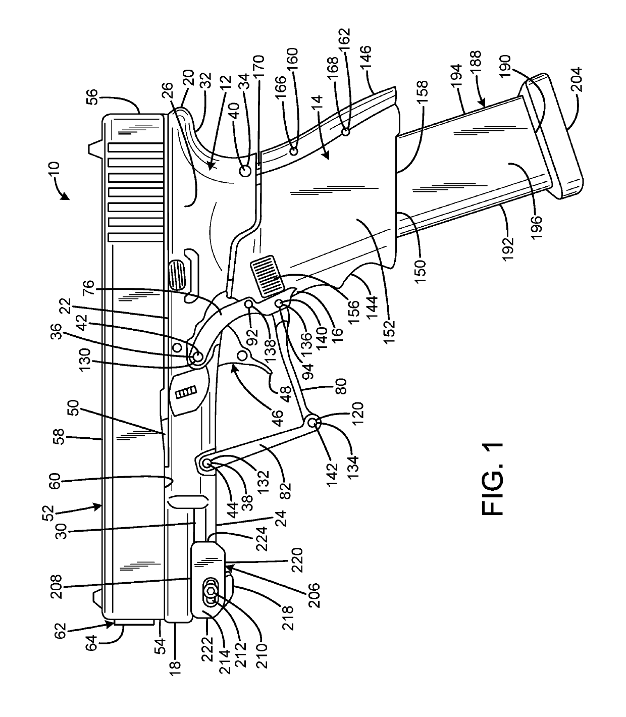
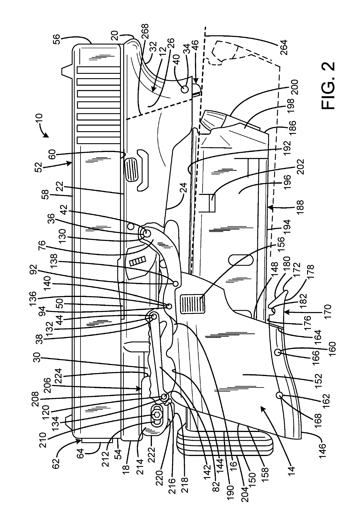
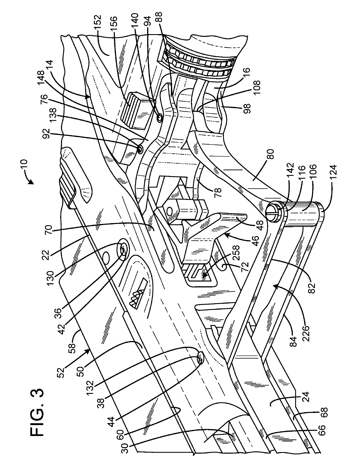
[0019]FIGS. 1-7 illustrate the improved folding pistol 10 of the present invention. More particularly, in the current embodiment, the folding pistol is a modified Glock 19 Gen4 pistol manufactured by Glock, Inc of Smyrna, Ga. This type of pistol has a 1-piece integrally molded plastic planar frame 12 including a unitary molded plastic handgrip 14 with a curved exterior to be comfortably received in a user's hand and a trigger guard 16. The folding pistol of the present invention detaches the handgrip from the frame, cuts off most of the trigger guard to leave only a small stub on the handgrip, and adds numerous slots and apertures that will be described subsequently.

[0020]FIGS. 1 & 3 show the folding pistol 10 with the handgrip 14 in the extended position in which the pistol is operable. The frame 12 has a front 18, rear 20, top 22, bottom 24, left side 26...


PUM


Abstract

A folding pistol has a frame having slide rails adapted to receive a slide, a grip defining a magazine passage pivotally connected to the frame at a first pivot and having a free end extending away from the first pivot, the grip being movable between an extended position in which the pistol is operable, and a stowed position in which the free end of the grip is adjacent the frame, a forward trigger guard element pivotally connected to the frame at a second pivot, a lower trigger guard element connected to the forward trigger guard element at a third pivot, and the lower trigger guard element connected to the grip at a fourth pivot. The first, second, third, and fourth pivots may be at different locations. There may be a trigger connected to the frame at a selected one of the first, second, third, and fourth pivots.

Description

CROSS-REFERENCE TO RELATED APPLICATION[0001]This application claims the benefit of U.S. Provisional Patent Application No. 62 / 537,466 filed on Jul. 27, 2017, entitled “FOLDING HANDGUN & GRIP EXTENSION SECTIONS,” which is hereby incorporated by reference in its entirety for all that is taught and disclosed therein.FIELD OF THE INVENTION[0002]The present invention relates to firearms, and more particularly to a pistol that folds into a compact shape for storage or transport that is not readily identifiable as a handgun. The folding capability also provides a large physical and visual safety mechanism when the pistol is in the folded condition that supplements an additional mechanical safety that functions when the pistol is partially or fully unfolded.BACKGROUND OF THE INVENTION[0003]Concealed carry is the practice of carrying a firearm, usually a handgun, in public in a concealed manner. All 50 states in the US have laws allowing qualified individuals to carry certain concealed firea...

Claims


Application Information

Patent Timeline
Patent Type & Authority Patents(United States)
IPC IPC(8): F41A11/04F41C9/02F41C23/10
CPCF41A11/04F41C23/10F41C9/02F41A19/11F41C3/00
Inventor FULL, MICHAEL
Owner BATTLEARMS IP LLC
Learn More