Universal serial bus circuit

US10360174B1Active Publication Date: 2019-07-23VIA LABS INC
2 Cites 0 Cited by

Patent Information

Authority / Receiving Office
US · United States
Current Assignee / Owner
Publication Date
2019-07-23

Smart Images

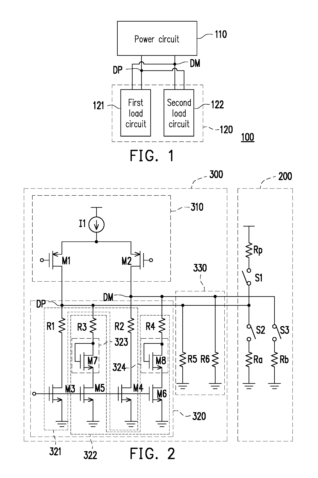
  • Figure 1
    Figure 1
  • Figure 2
    Figure 2
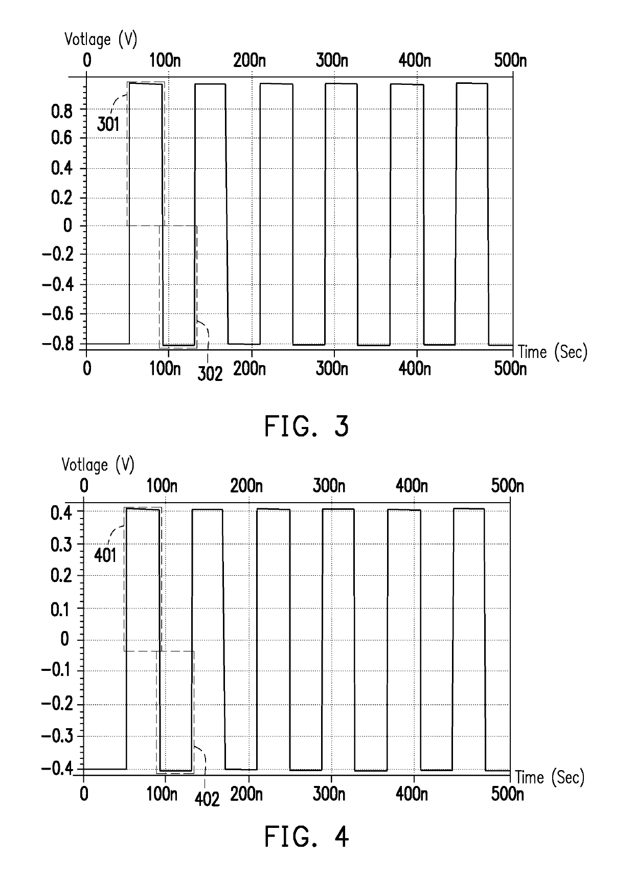
  • Figure 3
    Figure 3
Patent Text Reader

Abstract

A universal serial bus circuit including a power circuit and a terminating circuit is provided. The power circuit provides a differential signal. The terminating circuit is coupled to the power circuit. The terminating circuit receives the differential signal through the first signal output terminal and the second signal output terminal, and the terminating circuit includes a first load circuit and a second load circuit. When the universal serial bus circuit is operated in a handshake mode, the terminating circuit receives the differential signal through the first load circuit and the second load circuit, and outputs a pulse signal through the first signal output terminal and the second signal output terminal. When the universal serial bus circuit is operated in a normal mode, the terminating circuit receives the differential signal through the first load circuit, and outputs a data signal through the first signal output terminal and the second signal output terminal.
Need to check novelty before this filing date? Find Prior Art

Description

CROSS-REFERENCE TO RELATED APPLICATION

[0001] This application claims the priority benefit of Taiwan application serial no. 107125973, filed on Jul. 27, 2018. The entirety of the above-mentioned patent application is hereby incorporated by reference herein and made a part of this specification.BACKGROUND OF THE INVENTION1. Field of the Invention

[0002] The invention relates to a bus circuit, and more particularly, to a USB (Universal Serial Bus) circuit.2. Description of Related Art

[0003] In general, USB (Universal Serial Bus) 2.0 supports full speed and high speed data transmissions. Under the USB 2.0 standard, when a USB device served as a host is coupled to a device side equipment, the USB device and the device side equipment would first perform a handshake mode to confirm each other's data transmission capabilities. That is to say, before performing a transmission task for a data signal, the USB device served as the host would alternately transmit negative pulse signals and positive ...

Examples

Embodiment Construction

[0017]Reference will now be made in detail to the present preferred embodiments of the invention, examples of which are illustrated in the accompanying drawings. Wherever possible, the same reference numbers are used in the drawings and the description to refer to the same or like parts.

[0018]In order to make content of the invention more comprehensible, embodiments are described below as the examples to prove that the invention can actually be realized. Moreover, elements / components / steps with same reference numerals represent same or similar parts in the drawings and embodiments.

[0019]FIG. 1 is a schematic diagram of a USB circuit according to an embodiment of the invention. With reference to FIG. 1, a USB (Universal Serial Bus) circuit 100 includes a power circuit 110 and a terminating circuit 120. The power circuit 110 is coupled to the terminating circuit 120. In this embodiment, the terminating circuit 120 includes a first load circuit 121 and a second load circuit 122. The po...