
Hydrogen generating apparatus and hydrogen generating method

Active Publication Date: 2012-02-16
TOYOTA JIDOSHA KK +1
View PDF4 Cites 14 Cited by
  • Summary
  • Abstract
  • Description
  • Claims
  • Application Information

AI Technical Summary

Benefits of technology

[0007]The present invention provides a hydrogen generating apparatus and a h

Problems solved by technology

However, since hydrogen occupies a large volume when stored, a means for feeding hydrogen as a fuel has been problematic, especially for fuel cells for automobiles.

Method used


Image

  • Hydrogen generating apparatus and hydrogen generating method
  • Hydrogen generating apparatus and hydrogen generating method
  • Hydrogen generating apparatus and hydrogen generating method

Examples


first embodiment

the Hydrogen Generating Apparatus of the Present Invention

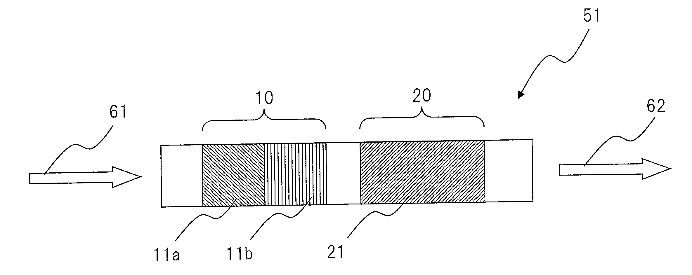
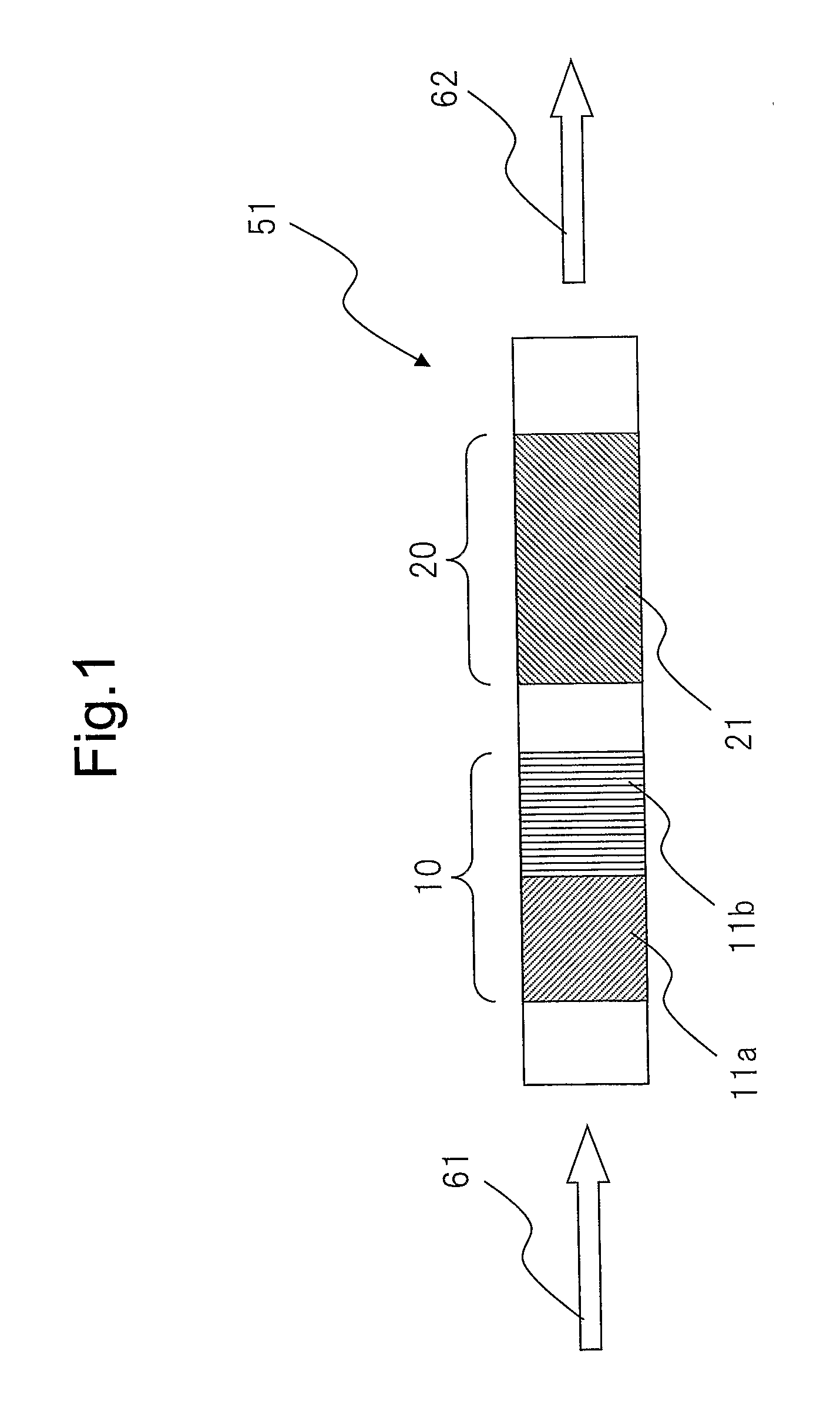
[0026]The hydrogen generating apparatus of the present invention can be configured, for example, as shown in FIG. 1. The first embodiment (51) of the hydrogen generating apparatus of the present invention shown in FIG. 1 has an ammonia oxidation part (10) having ammonia oxidation catalysts (11a, 11b) which oxidize ammonia, and an ammonia decomposition part (20) having an ammonia decomposition catalyst (21) which decomposes ammonia to generate nitrogen and hydrogen. In the hydrogen generating apparatus (51), a feed gas containing ammonia and oxygen is supplied as indicated by arrow 61, a product gas containing hydrogen is obtained as indicated by arrow 62, and therefore the ammonia decomposition part (20) is located downstream of the ammonia oxidation part (10) in the direction of the feed gas flow.

[0027]The feed gas containing ammonia and oxygen may be a mixed gas of ammonia and air. Further, in FIG. 1, the ammonia oxidation ...

second embodiment

the Hydrogen Generating Apparatus of the Present Invention

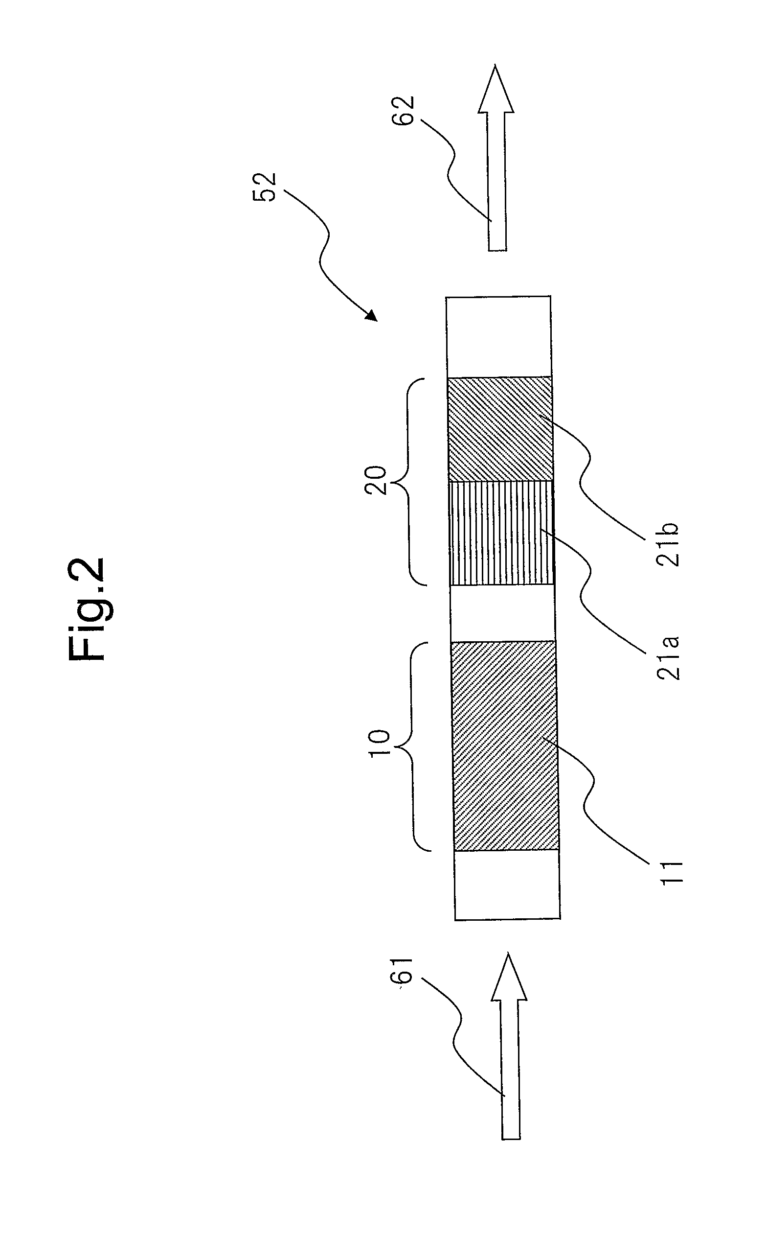
[0033]Further, the hydrogen generating apparatus of the present invention can be configured, for example, as shown in FIG. 2. The second embodiment (52) of the hydrogen generating apparatus of the present invention shown in FIG. 2 has an ammonia oxidation part (10) having an ammonia oxidation catalyst (11) which oxidizes ammonia, and an ammonia decomposition part (20) having ammonia decomposition catalysts (21a, 21b) which decompose ammonia to generate nitrogen and hydrogen. In the hydrogen generating apparatus (52), and a feed gas containing ammonia and oxygen is supplied as indicated by arrow 61, a product gas containing hydrogen is obtained as indicated by arrow 62, and therefore the ammonia decomposition part (20) is located downstream of the ammonia oxidation part (10) in the direction of the feed gas flow.

[0034]According to the hydrogen generating apparatus of the present invention, in the ammonia oxidation part, a port...

third embodiment

the Hydrogen Generating Apparatus of the Present Invention

[0039]Further, the hydrogen generating apparatus of the present invention can be configured, for example, as shown in FIG. 3. The third embodiment of the hydrogen generating apparatus (53) of the present invention shown in FIG. 3 has an ammonia oxidation part (10) having ammonia oxidation catalysts (11a, 11b) which oxidize ammonia, and an ammonia decomposition part (20) having ammonia decomposition catalysts (21a, 21b) which decompose ammonia to generate nitrogen and hydrogen. In the hydrogen generating apparatus (53), and a feed gas containing ammonia and oxygen is supplied as indicated by arrow 61, a product gas containing hydrogen is obtained as indicated by arrow 62, and therefore the ammonia decomposition part (20) is located downstream of the ammonia oxidation part (10) in the direction of the feed gas flow.

[0040]Further, the downstream portion (11b) of the ammonia oxidation part (10) in a direction of feed gas flow may...


PUM

PropertyMeasurementUnit
Temperatureaaaaaaaaaa

Abstract

A hydrogen generating apparatus for effectively generating hydrogen from ammonia and relates to the hydrogen generating apparatus for generating hydrogen from ammonia. The apparatus comprises an ammonia oxidation part having ammonia oxidation catalysts which oxidizes ammonia, and an ammonia decomposition part having an ammonia decomposition catalyst which decomposes ammonia to generate nitrogen and hydrogen. The decomposition part is located downstream of the oxidation part in a direction of feed gas flow. The oxidation catalyst contains both a noble metal catalyst and a base metal catalyst, and a loading concentration of the noble metal catalyst in an upstream portion of the oxidation part is higher than a loading concentration of the noble metal catalyst in a downstream portion of the oxidation part, and / or the decomposition catalyst contains both a noble metal catalyst and a base metal catalyst, and a loading concentration of the noble metal catalyst in a downstream portion of the decomposition part is higher than a loading concentration of the noble metal catalyst in an upstream portion of the decomposition part.

Description

TECHNICAL FIELD[0001]The present invention relates to a hydrogen generating apparatus, and more specifically, a hydrogen generating apparatus suitable for an automobile. Further, the present invention relates to a hydrogen generating method using such a hydrogen generating apparatus.BACKGROUND ART[0002]Recently, it has been proposed to use hydrogen as a clean energy source. Particularly, automobiles powered by fuel cells using hydrogen as fuel are being actively developed. The exhaust gas from fuel cells using hydrogen as fuel does not contain nitrogen oxide, particulate matter (PM), carbon dioxide, etc., which are contained in the exhaust gas from an internal combustion engine, and therefore such fuel cells are suitable as a clean power source which can prevent environmental pollution and global warming.[0003]However, since hydrogen occupies a large volume when stored, a means for feeding hydrogen as a fuel has been problematic, especially for fuel cells for automobiles.[0004]In co...

Claims


Application Information

Patent Timeline
IPC IPC(8): H01M8/06B01J7/00C01B3/04F02B43/10
CPCB01J8/0221Y02E60/364B01J21/04B01J23/42B01J23/44B01J23/462B01J23/745B01J23/755B01J35/023B01J2208/00061B01J2208/00274B01J2208/025C01B3/047C01B2203/06C01B2203/066C01B2203/1041C01B2203/1047C01B2203/1052C01B2203/1058C01B2203/1064C01B2203/107B01J8/0438Y02E60/36B01J35/40
Inventor NAKANISHI, HARUYUKIARIKAWA, HIDEKAZUHIKAZUDANI, SUSUMUINAZUMI, CHIKASHIARAKI, SADAOMORI, TAKUMA
Owner TOYOTA JIDOSHA KK
Learn More