
Motion detecting device and search region variable-shaped motion detector

Inactive Publication Date: 2004-08-26
RENESAS ELECTRONICS CORP
View PDF7 Cites 16 Cited by
  • Summary
  • Abstract
  • Description
  • Claims
  • Application Information

AI Technical Summary

Benefits of technology

[0007] It is an object of the present invention to provide a motion detecting device capable of effectively generating a motion vector.
[0009] The motion vector is obtained while varying the determined search shape at the predetermined timing as the overall motion information varies. Thus, it is possible to obtain the motion vector of high accuracy with effective processing.
[0012] The motion vector is obtained while varying the determined search shape at the predetermined timing as the overall motion information varies. Thus, it is possible to obtain the motion vector of high accuracy with effective processing.

Problems solved by technology

This is one of factors that disadvantageously prevent effective generation of a motion vector.

Method used


Image

  • Motion detecting device and search region variable-shaped motion detector
  • Motion detecting device and search region variable-shaped motion detector
  • Motion detecting device and search region variable-shaped motion detector

Examples


Embodiment Construction

[0046] First Preferred Embodiment

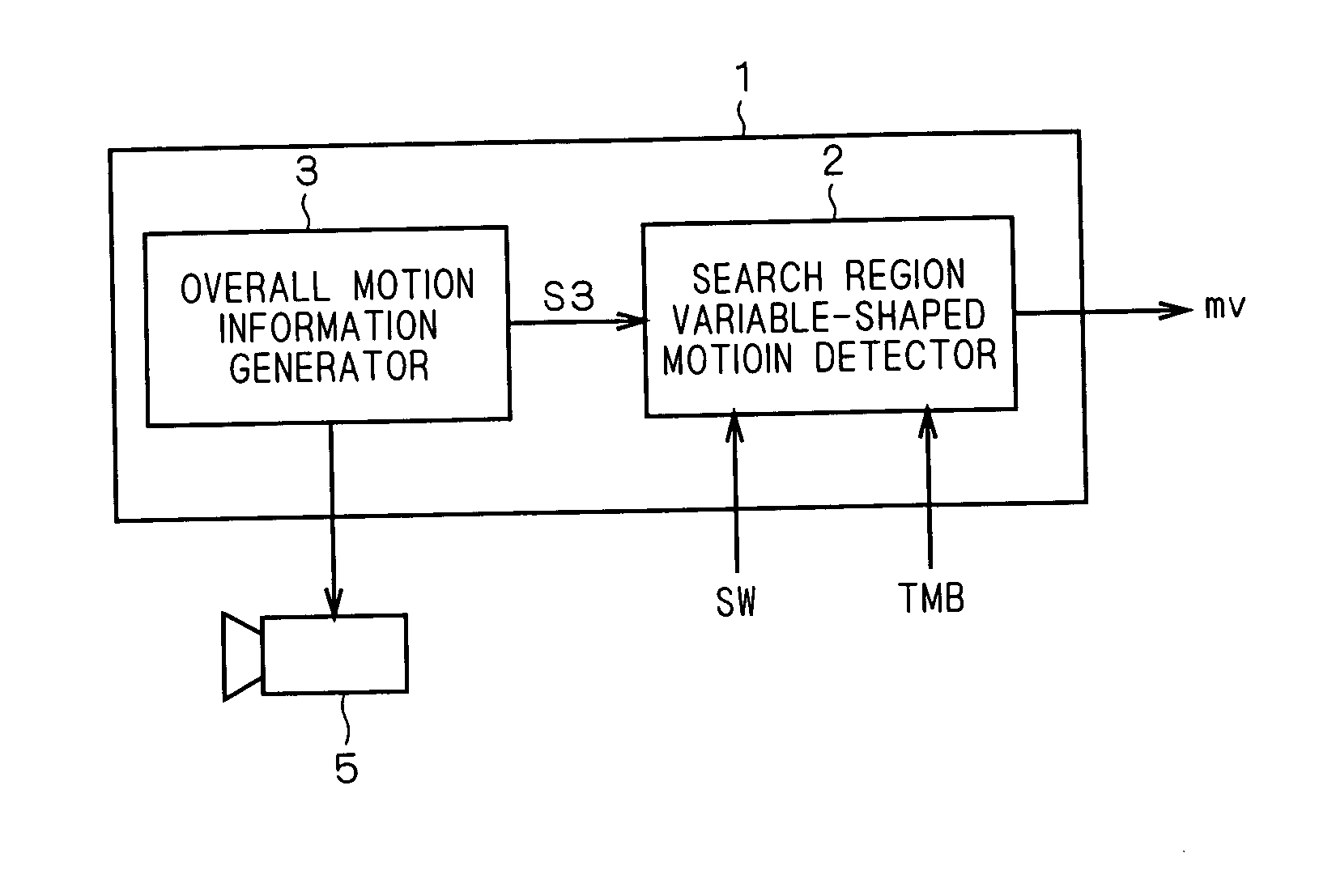
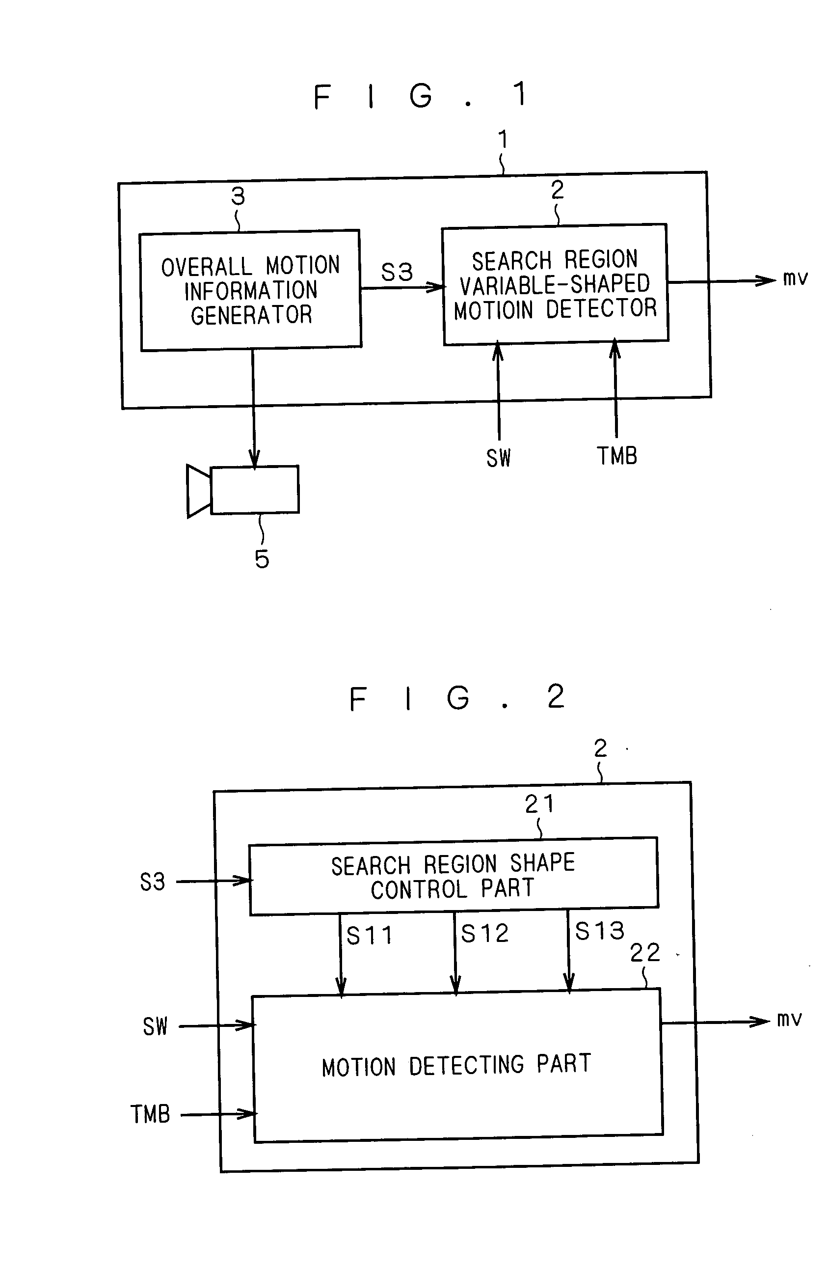
[0047] FIG. 1 is a block diagram illustrating the configuration of a motion detecting device according to a first preferred embodiment of the present invention. As shown, a motion detecting device 1 includes a search region variable-shaped motion detector 2 and an overall motion information generator 3. The generator 3 controls a surveillance camera 5 which is an external image capturing system.

[0048] The overall motion information generator 3 supplies control information of the surveillance camera 5 (such as moving direction, angular speed and focal length) to the search region variable-shaped motion detector 2 as overall motion information S3.

[0049] For instance, the motion of the surveillance camera 5 is generally controlled by control information of a microcontroller. Thus, the overall motion information generator 3 having the function of such microcontroller may supply the search region variable-shaped motion detector 2 with the control informat...


PUM


Abstract

An overall motion detecting device (1) includes a search region variable-shaped motion detector (2) and an overall motion information generator (3). The overall motion information generator (3) controls a surveillance camera (5) which is an external image capturing system and supplies control information of the surveillance camera (5) (such as moving direction, angular speed and focal length) to the search region variable-shaped motion detector (2) as overall motion information (S3). The search region variable-shaped motion detector (2) calculates a motion vector (mv) while renewing, by picture, a search region having a search shape determined by the overall motion information (S3) and a region area suitable for its operational capability.

Description

BACKGROUND OF THE INVENTION[0001] 1. Field of the Invention[0002] The present invention relates to a motion detecting device for generating a motion vector, applicable to video encoding standards using motion compensation such as MPEG-1, MPEG-2 and MPEG-4.[0003] 2. Description of the Background Art[0004] Among conventional motion (vector) detecting devices for determining search ranges is an optimum motion vector search section in a video encoding device disclosed in Japanese Patent Application Laid-Open No. 11-252571 (1999).[0005] This optimum motion vector search section includes a search range determining part and a predicted motion vector peripheral search part. The search range determining part obtains the size of search range based on an allowable calculation amount given by an external control part. The predicted motion vector peripheral search part determines the shape of search region based on the distribution of motion vectors already obtained, and the size of search range...

Claims


Application Information

Patent Timeline
IPC IPC(8): H04N5/14H04N5/225H04N19/105H04N19/139H04N19/156H04N19/176H04N19/189H04N19/50H04N19/51H04N19/57
CPCG06T2207/10016G06T2207/30232H04N5/145G06T7/223H04N19/61H04N19/543H04N19/57H04N7/183
Inventor HANAMI, ATSUO
Owner RENESAS ELECTRONICS CORP
Learn More