Control device and control method

a control device and control method technology, applied in the direction of electric generator control, dynamo-electric converter control, dynamo-electric gear control, etc., can solve the problems of not being suitable for an embedded motor control device and high cost of current sensors

Active Publication Date: 2019-08-13
CANON KK
View PDF4 Cites 0 Cited by
  • Summary
  • Abstract
  • Description
  • Claims
  • Application Information

AI Technical Summary

Benefits of technology

[0009]An aspect of the present invention provides a motor control technique capable of suppressing or removing a failure in current detection.
[0011]According to an exemplary aspect of the present invention, it is possible to provide the motor control technique capable of suppressing or removing the failure in current detection.

Problems solved by technology

However, the current sensor is expensive, and thus not suitable for an embedded motor control device.

Method used


Image

  • Control device and control method
  • Control device and control method
  • Control device and control method

Examples


first embodiment

[0030](First Embodiment)

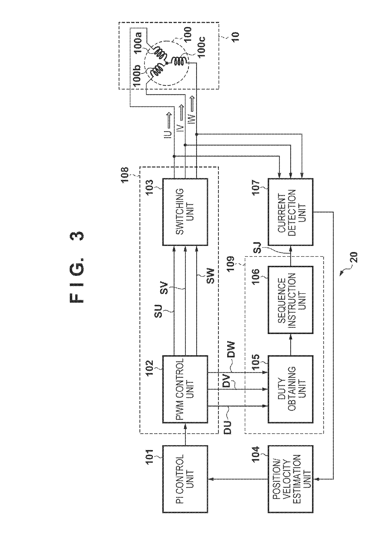
[0031]FIG. 3 is a block diagram showing the functions and arrangements of a control device 20 and a three-phase motor 10 controlled by it according to the first embodiment. Each block of the control device 20 shown here can be implemented as hardware by an element or a machine device such as a CPU of a computer and can be implemented as software by a computer program or the like. However, a functional block implemented by cooperation between them is illustrated here. Therefore, those who are skilled in the art and who read this specification understand that these functional blocks can be implemented in various ways by a combination of hardware and software.

[0032]The three-phase motor 10 is a three-phase brushless motor, and includes a three-phase coil 100 and other members such as a rotor and a stator (neither is shown). The three-phase coil 100 includes a U-phase coil 100a, a V-phase coil 100b, and a W-phase coil 100c. In FIG. 3, each of the coils 100a, 100b...

second embodiment

[0056](Second Embodiment)

[0057]In the first embodiment, a case has been described in which the duty obtaining unit 105 obtains the duties from the PWM control unit 102. In the second embodiment, a phase of a voltage output to a three-phase coil 100 is classified for each sector, and the sequence of phases for detecting currents is changed for each sector.

[0058]FIG. 7 is a block diagram showing the functions and arrangements of a control device 920 and a three-phase motor 10 controlled by it according to the second embodiment. The control device 920 includes a PI control unit 101, a driving unit 108, a current detection unit 107, a change unit 909, and a position / velocity estimation unit 104. The change unit 909 discriminates a sector based on a current detected by the current detection unit 107 and obtains a duty corresponding to the discriminated sector. In accordance with the thus obtained duty, the change unit 909 changes the current detection sequence in the current detection un...


PUM


Abstract

A control device comprises a driving unit configured to drive a plurality of coils of a multiple-phase motor by pulse width modulation; a detection unit configured to detect currents flowing through the plurality of coils in a time-division manner; and a change unit configured to change, in accordance with a duty in the pulse width modulation, a sequence of detecting the currents flowing through the plurality of coils by the detection unit.

Description

BACKGROUND OF THE INVENTION[0001]Field of the Invention[0002]The present invention relates to a control device and a control method.[0003]Description of the Related Art[0004]A three-phase brushless motor is known as one type of three-phase (a U phase, a V phase, and a W phase) motor. The three-phase brushless motor free from wear of brush is high in durability and widely used. In a general three-phase brushless motor, a rotation torque is generated by supplying a three-phase AC current to a three-phase coil. In recent years, it is possible to implement improvements in quietness and driving efficiency by performing current-drive control using a sine wave. Furthermore, vector control of controlling the amplitude and phase of a three-phase sinusoidal current precisely is becoming quite common.[0005]In this vector control, the three-phase brushless motor is driven by pulse width modulation (to be referred to as PWM hereinafter) in which a switching element of an inverter undergoes an ON...

Claims


Application Information

Patent Timeline
Patent Type & Authority Patents(United States)
IPC IPC(8): H02P27/12H02P21/22H02P21/18H02P6/28H02P6/18
CPCH02P27/12H02P6/18H02P21/18H02P21/22H02P6/28H02P2203/09
Inventor KAWAMURA, KOJIASHIDA, JUMPEIKAMEYAMA, SHIGERU
Owner CANON KK
Why Eureka
Try Eureka