Dynamically balanced seat assembly having independently and arcuately movable backrest and method

a backrest and dynamically balanced technology, applied in the field of seat assemblies, can solve the problems of unsafe seat as well as uncomfortable, not being able to observe, and not being able to adjust to the body's motion, etc., and achieve the effect of relaxing safely

Active Publication Date: 2019-08-20
SERBER HECTOR
View PDF5 Cites 8 Cited by
  • Summary
  • Abstract
  • Description
  • Claims
  • Application Information

AI Technical Summary

Benefits of technology

[0017]The chair mechanism of the present invention is designed to match the motion of the body with the motion of the seat to allow the body to relax safely. It is a goal of the present mechanism to self-adjusts to an optimum position maintaining support without the need for manual adjustments at every instance of posture change. It is a further goal to accommodate the range of motion of the seated body with the present mechanism function of the seat and back.
[0022]The first three embodiments use the same underseat mounting assembly with independent movement of the backrest achieved alternately, as in FIG. 1, the backrest mounting assembly mounted to a backrest support slider that moves along a vertically extending arcuate upright bar that connects to the base assembly below the seat; or as in FIG. 16, the backrest mounting assembly pivotally mounted to a backrest support slider that slides along an extending linear upright bar that connects to the base assembly below the seat; or as in FIG. 6, the backrest is mounted to a horizontally extending U-Shaped backrest support structure that attaches at two uprights above the right and left sides of the seat at the arm support to frame members that connect to the base assembly below the seat.
[0029]The goal of the Present Invention is to facilitate essential body motion while sitting with mid range continuous support through the body's motions, maintaining the neutral posture between upright and reclined seated positions. The Dynamic Seat design seeks equilibrium and is self-adjusting, maintaining proper seat and lumbar support. The support surfaces come to rest and hold the posture to reduce muscle and bone stress where the body stops to either work or relax.

Problems solved by technology

Such chairs are not responsive to the body's motion.
This makes the seat unsafe as well as uncomfortable.
It is not enough to observe that movable seat and / or seat backs are known in the prior art.

Method used


Image

  • Dynamically balanced seat assembly having independently and arcuately movable backrest and method
  • Dynamically balanced seat assembly having independently and arcuately movable backrest and method
  • Dynamically balanced seat assembly having independently and arcuately movable backrest and method

Examples


Embodiment Construction

[0052]Reference will now be made in detail to the preferred embodiments of the invention, examples of which are illustrated in the accompanying drawings. While the invention will be described in conjunction with the preferred embodiments, it will be understood that they are not intended to limit the invention to those embodiments. On the contrary, the invention is intended to cover alternatives, modifications and equivalents, which may be included within the spirit and scope of the invention as defined by the appended claims.

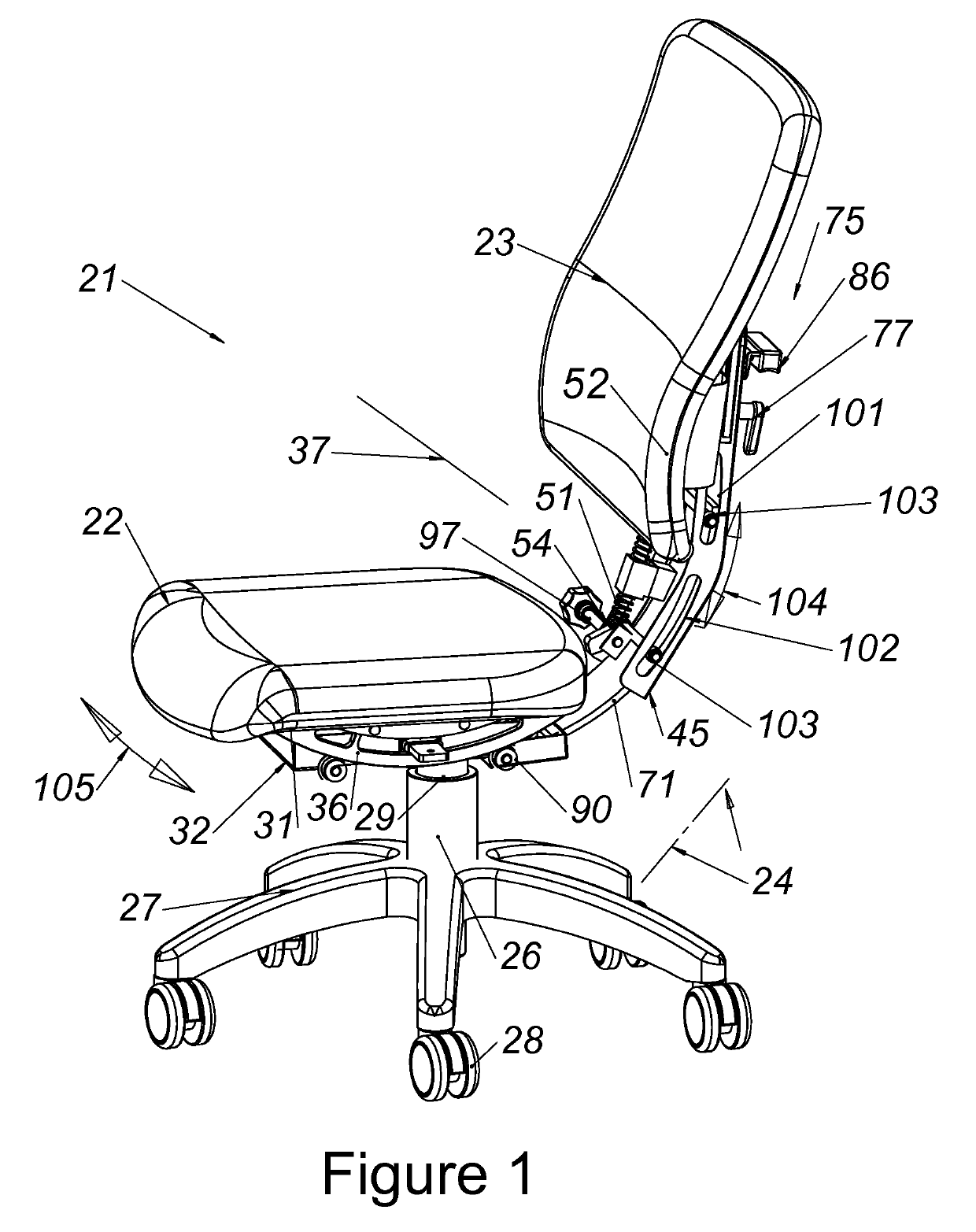
[0053]The seat assembly of the present invention employs a mounting assembly which allows the seat to move independently along an upwardly concaved arcuate path having a center of rotation above the seat and proximate the center of gravity of the user or person seated on the seat. This center of rotation for the seat is broadly known in the prior art, as indicated above, and enables the user to periodically adjust the seat position while maintaining the mass of ...


PUM

PropertyMeasurementUnit
center of curvatureaaaaaaaaaa
weightaaaaaaaaaa
structureaaaaaaaaaa

Abstract

A seat assembly including a seat, a backrest and a mounting assembly mounting the seat in a near horizontal orientation for movement along an upwardly concaved arcuate seat path having a center of curvature proximate the center of mass of a person seated on the seat, and mounting assembly further mounting the backrest in a near vertical orientation for movement independently of the seat along a forwardly concaved arcuate path having a center curvature proximate the center of mass of the person. An adjustment assembly is provided for adjusting the radius of curvature of the path of motion of the backrest. Also provided are a backrest tilt adjustment assembly, an armrest adjustment assembly, a seat biasing assembly and a seat motion latching assembly. A method of self-adjusting support and alignment of a backrest also is disclosed.

Description

CROSS-REFERENCES TO RELATED APPLICATIONS[0001]The present patent application is a continuation-in-part application based on copending parent patent application Ser. No. 11 / 973,914, filed on Oct. 10, 2007 with Notice of Allowance mailed Sep. 23, 2013, now U.S. Pat. No. 8,662,586 and entitled “DYNAMICALLY BALANCED SEAT ASSEMBLY HAVING INDEPENDENTLY AND ARCUATELY MOVABLE BACKREST AND METHOD,” the entire content of which is incorporated herewith by this reference. The patent application is in condition for allowance for Claims 1-12. This application seeks to re-claim the withdrawn claims and additional matter not claimed before herewith.[0002]This applicant inventor was granted U.S. Pat. No. 7,234,775 B2 in 2007. This patent is related to the present application wherein Claim 1 was granted representing a special case of the supporting structure design. An important object of the present application is to incorporate the design of several other supporting structures invented to produce t...

Claims


Application Information

Patent Timeline
Patent Type & Authority Patents(United States)
IPC IPC(8): A47C9/00A47C1/023A47C1/024A47C3/027A47C3/026A47C3/025
CPCA47C3/0257A47C1/023A47C1/024A47C3/027A47C9/002A47C3/026Y10T29/49826
Inventor SERBER, HECTOR
Owner SERBER HECTOR
Why Eureka
Try Eureka