Physical unclonable function using divided threshold distributions in non-volatile memory
What is Al technical title?
Al technical title is built by PatSnap Al team. It summarizes the technical point description of the patent document.
a threshold distribution and non-volatile memory technology, applied in the field of integrated circuits, can solve the problem of inacceptable bit error rate when accessing or using stored keys, and achieve the effect of improving the flexibility and reliability of security circuitry
Active Publication Date: 2019-09-03
MACRONIX INT CO LTD
View PDF72 Cites 6 Cited by
Summary
Abstract
Description
Claims
Application Information
AI Technical Summary
This helps you quickly interpret patents by identifying the three key elements:
Problems solved by technology
Method used
Benefits of technology
[0015]A physical unclonable function is described using divided threshold distributions in non-volatile memory, such as flash memory. Also, devices and systems are described which can improve the flexibility and reliability of security circuitry that utilizes physical unclonable functions, and random keys in general. The devices and systems described herein are suitable for use in internet of things devices, and can be implemented in a wide variety of environments.
[0017]A method is provided for generating a data set usable as a unique identifier or key, on an integrated circuit using charge trapping non-volatile memory cells including floating gate and dielectric charge trapping technologies, and in some embodiments using other types of non-volatile memory cells. The method can include a physical unclonable function which results in establishing variant thresholds, such as threshold voltages, within memory cells in the set. The method can be used to produce a stable, PUF-based data sets, usable with zero or very low bit error rates.
Problems solved by technology
However, in this ReRAM-based PUF, the data created can still be corrupted by drift in the resistance of the memory cells, which can make a bit error rate unacceptable when accessing or using the stored key.
Method used
Image
Click on the blue label to locate the original text in one second.
Reading with bidirectional positioning of images and text.
Examples
Embodiment Construction
[0051]A detailed description of embodiments of the present technology is provided with reference to the Figures. It is to be understood that there is no intention to limit the technology to the specifically disclosed structural embodiments and methods but that the technology may be practiced using other features, elements, methods and embodiments. Preferred embodiments are described to illustrate the present technology, not to limit its scope, which is defined by the claims. Those of ordinary skill in the art will recognize a variety of equivalent variations on the description that follows. Like elements in various embodiments are commonly referred to with like reference numerals.
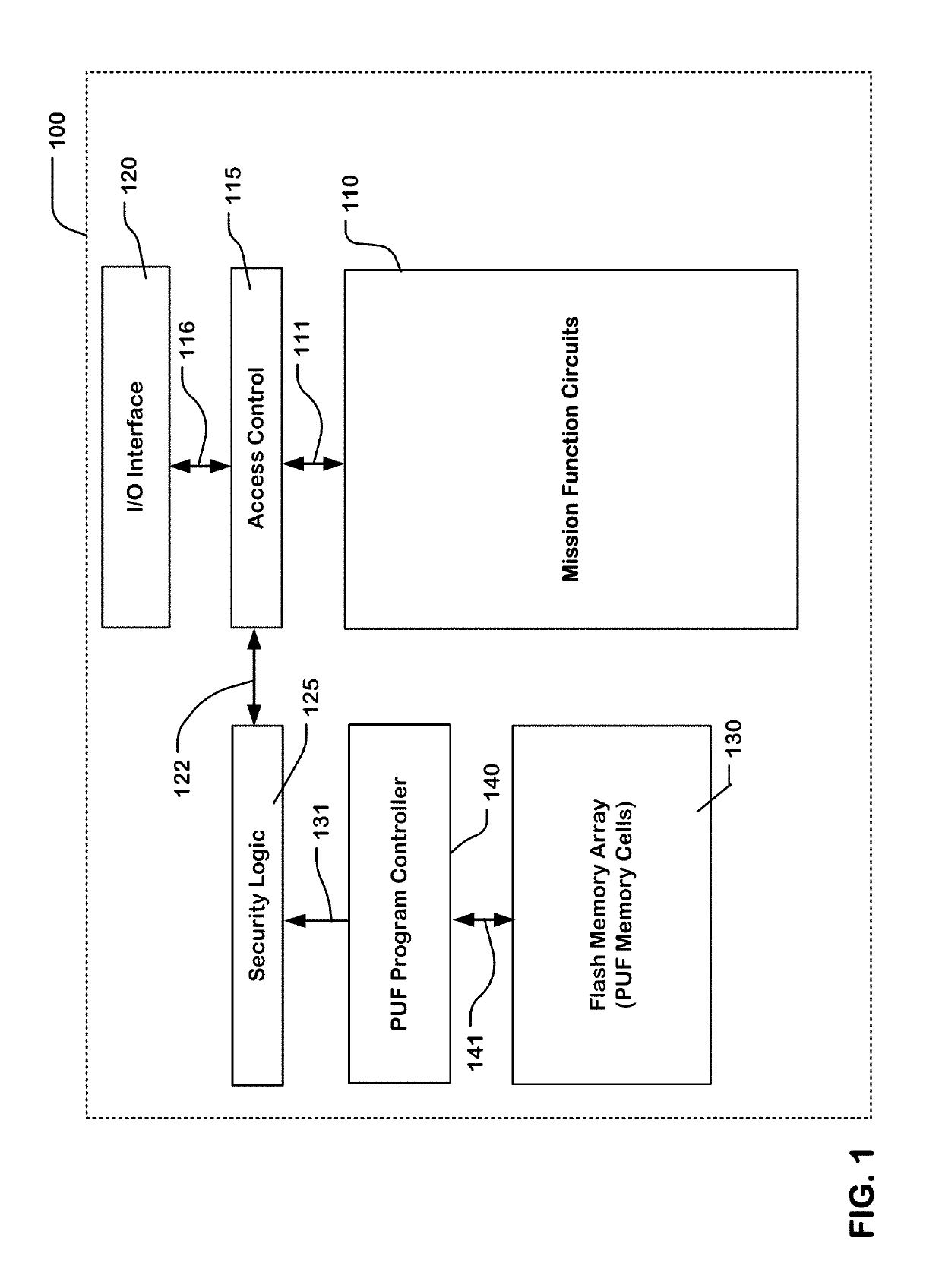
[0052]FIG. 1 is a simplified block diagram of an apparatus comprising a plurality of programmable memory cells, and a controller for executing a process to provide a data set using the plurality of programmable memory cells. In this example, the apparatus comprises an integrated circuit 100 having a memory ...
PUM
Abstract
A system and method for utilizing a security key stored in non-volatile memory, and for generating a PUF-based data set on an integrated circuit including non-volatile memory cells, such as flash memory cells, are described. The method includes storing a security key in a particular block in a plurality of blocks of the non-volatile memory array; utilizing, in a security logic circuit coupled to the non-volatile memory array, the security key stored in the particular block in a protocol to enable access via a port by external devices or communication networks to data stored in blocks in the plurality of blocks; and enabling read-only access to the particular block by the security logic for use in the protocol, and preventing access to the particular block via the port.
Description
PRIORITY APPLICATIONS[0001]Benefit of U.S. provisional applications is hereby claimed, including:[0002]U.S. Provisional Application No. 62 / 370,736, filed Aug. 4, 2016, entitled NVM-based Physically Unclonable Function;[0003]U.S. Provisional Application No. 62 / 423,753, filed Nov. 17, 2016, entitled NVM-based Physically Unclonable Function;[0004]U.S. Provisional Application No. 62 / 430,196, filed Dec. 5, 2016, entitled Non-Volatile Memory Based Physical Unclonable Function;[0005]U.S. Provisional Application No. 62 / 431,835, filed Dec. 9, 2016, entitled Flash-based Physically Unclonable Function;[0006]U.S. Provisional Application No. 62 / 435,092, filed Dec. 16, 2016, entitled Stable Physically Unclonable Function; and[0007]U.S. Provisional Application No. 62 / 435,337, filed Dec. 16, 2016, entitled Non-Volatile Memory Based Physical Unclonable Function.BACKGROUNDField of the Invention[0008]The present invention relates to integrated circuits which include flash memory arrays or other non-vo...
Claims
Application Information
Patent Timeline
Application Date:The date an application was filed.
Publication Date:The date a patent or application was officially published.
First Publication Date:The earliest publication date of a patent with the same application number.
Issue Date:Publication date of the patent grant document.
PCT Entry Date:The Entry date of PCT National Phase.
Estimated Expiry Date:The statutory expiry date of a patent right according to the Patent Law, and it is the longest term of protection that the patent right can achieve without the termination of the patent right due to other reasons(Term extension factor has been taken into account ).
Invalid Date:Actual expiry date is based on effective date or publication date of legal transaction data of invalid patent.