
Integrated circuit and operating method therefor

Inactive Publication Date: 2007-08-09
ATMEL GERMANY
View PDF4 Cites 0 Cited by
  • Summary
  • Abstract
  • Description
  • Claims
  • Application Information

AI Technical Summary

Benefits of technology

[0006]It is an object of the present invention to provide an integrated circuit having increased flexibility and reliability.

Problems solved by technology

It is also conceivable to deactivate the level converter when it is suspected that the second circuit component has a disruption of operation or another defect.

Method used


Image

  • Integrated circuit and operating method therefor
  • Integrated circuit and operating method therefor
  • Integrated circuit and operating method therefor

Examples


Embodiment Construction

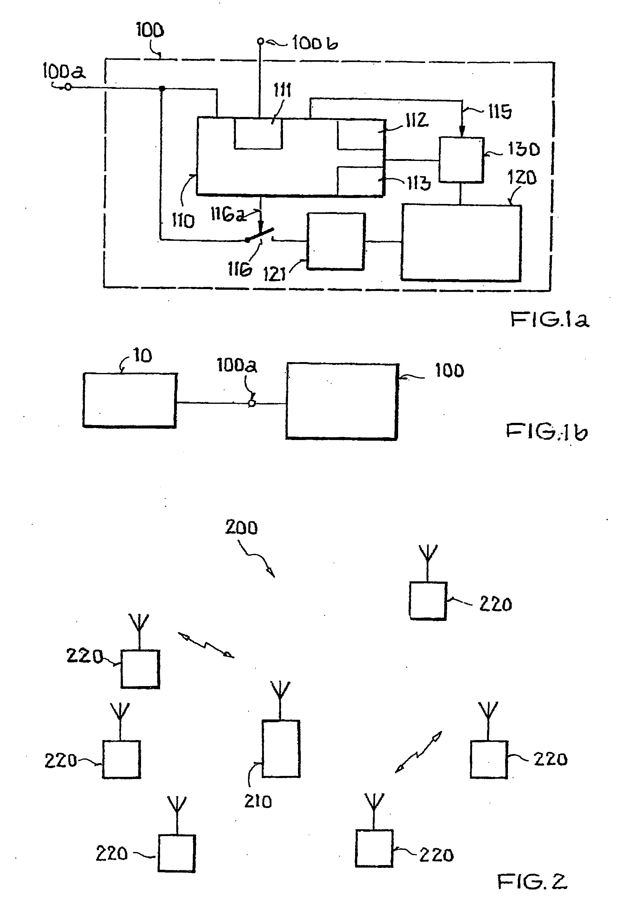
[0045]FIG. 1a shows schematically a block diagram of an integrated circuit 100 of the invention. Integrated circuit 100 has a first circuit component 110, which is connected via a level converter 130 to a second circuit component 120. The connection has one or more data or control lines, which are not described in greater detail, by which signals are transmitted between the first and the second circuit component.

[0046]First circuit component 110 is realized using a CMOS semiconductor technology with feature sizes of about 0.36 μm and therefore has an operating voltage range of about 1.8 V to about 3.75 V. A voltage supply of first circuit component 110 of integrated circuit 100 can therefore occur via an external voltage source (not shown in FIG. 1a) directly connected to terminal 100a.

[0047]Second circuit component 120 is realized using a CMOS semiconductor technology with feature sizes of about 0.18 μm and therefore has an operating voltage range of about (1.8±10%) V. Accordingly...


PUM


Abstract

An integrated circuit is provided that includes at least one first circuit component and at least one second circuit component, the first circuit component being connected via a level converter to the second circuit component. The level converter can be optionally activated or deactivated by the first circuit component in order to enable or prevent a data exchange between the first circuit component and the second circuit component.

Description

[0001]This nonprovisional application claims priority under 35 U.S.C. § 119(a) to German Patent Application No. DE 102006005779, which was filed in Germany on Feb. 3, 2006, and which is herein incorporated by reference.BACKGROUND OF THE INVENTION[0002]1. Field of the Invention[0003]The present invention relates to an integrated circuit with at least one first circuit component and with at least one second circuit component, the first circuit component being connected via a level converter to the second circuit component. The invention relates furthermore to an operating method for an integrated circuit of this type.[0004]2. Description of the Background Art[0005]Integrated circuits are known in the art, and a level converter is typically used to convert the level of signals such as, e.g., the voltage level, which are exchanged between circuit components, connected to one another via the level converter, in appropriate data lines or control lines.SUMMARY OF THE INVENTION[0006]It is a...

Claims


Application Information

Patent Timeline
IPC IPC(8): H03K3/00
CPCH04W52/028Y02D30/70
Inventor DATHE, LUTZ
Owner ATMEL GERMANY
Learn More