Machining system

US20050224557A1Inactive Publication Date: 2005-10-13KUKA SYSTEMS

Image

  • Machining system
  • Machining system

Examples


Embodiment Construction

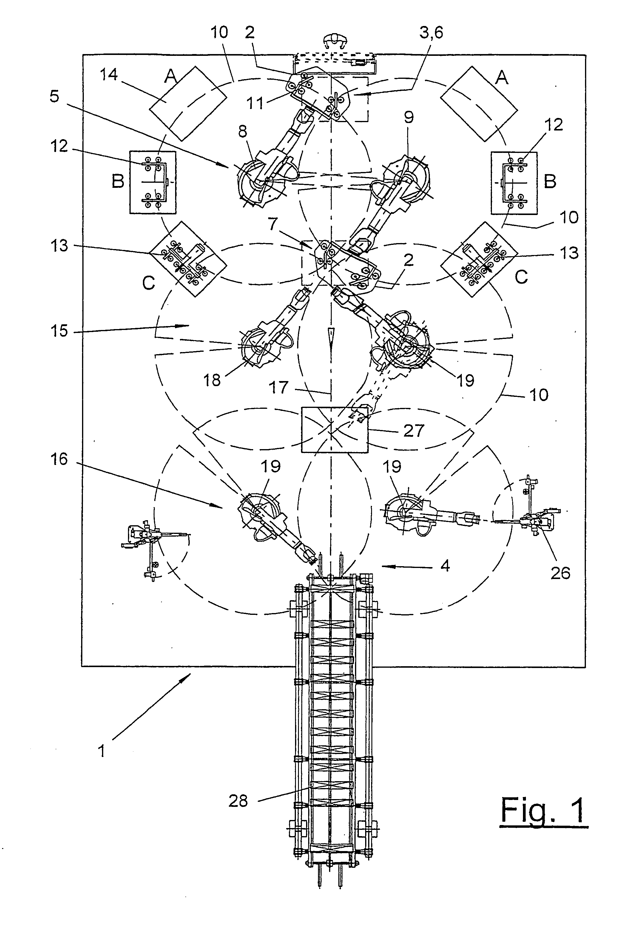
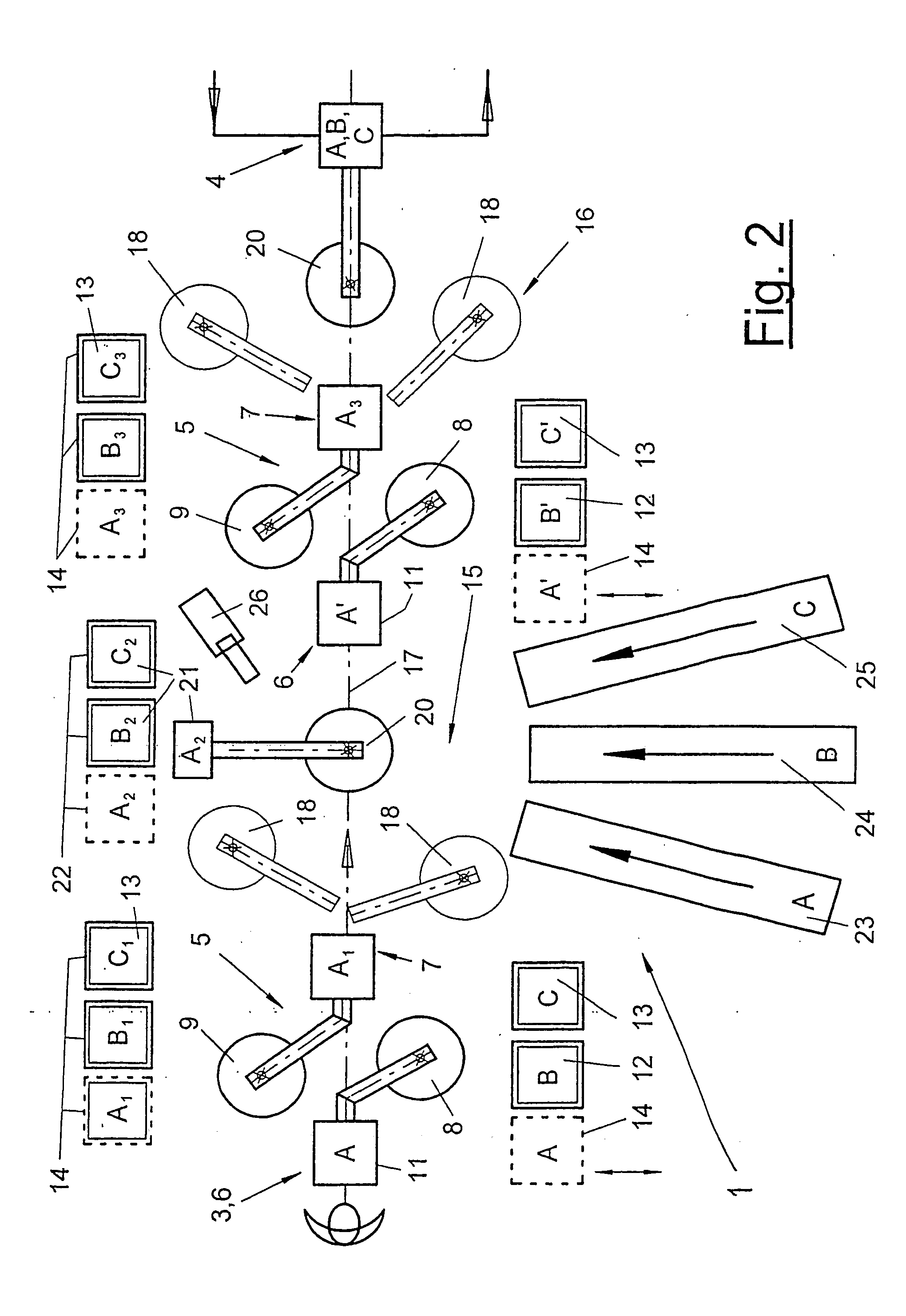
[0017] Referring to the drawings in particular, FIGS. 1 and 2 schematically show top views of a machining unit 1, here, e.g., a welding cell, for the multistep machining of workpieces 2. The workpieces 2 are parts of vehicle bodies or complete bodies. One or more turning stations 5 and one or more machining stations 15, 16 are arranged one after another along a transfer line 17 within the machining unit 1. The transfer line 17 may extend in a straight line, as in the exemplary embodiment being shown. As an alternative, it may also be bent at an angle. A manual or automatic workpiece feed means 3 is located at the inlet of the unit 1. A likewise manual or automatic workpiece discharge unit 4 is arranged on the outlet side. At least one worker, who feeds the workpieces 2 manually, introduces them and optionally introduces additional components at the workpiece, is located at the workpiece feed means 3 in the exemplary embodiments shown. The workpiece discharge unit 4 comprises a suita...


PUM

PropertyMeasurementUnit
Weightaaaaaaaaaa

Abstract

A machining system and unit, especially a welding cell, is provided for use for the machining of workpieces (2), especially body parts of vehicles. The machining system has one or more machining stations (15, 16) with robots (18, 19, 20) and at least one rotation or turning station (5), which has at least two work stations (6, 7) for carrying out different operations simultaneously. The turning station (5) has at least two said multiaxially movable turning units (8, 9) arranged next to one another with said gripping tools (11, 12, 13). The working areas (10) intersect each other at the work stations (6, 7).

Description

CROSS REFERENCE TO RELATED APPLICATIONS [0001] This application is a United States National Phase application of International Application PCT / EP2003 / 008016 and claims the benefit of priority under 35 U.S.C. § 119 of German Application DE 1202 11 755.3 filed Jul. 30, 2002, the entire contents of which are incorporated herein by reference.FIELD OF THE INVENTION [0002] The present invention pertains to a machining unit, especially a welding cell especially body parts of vehicles, with one or more machining stations with said robots and at least one turning station which has at least two said work stations for carrying out different operations simultaneously. BACKGROUND OF THE INVENTION [0003] Such machining units, especially welding cells, have been known from practice. They are used for the multistep machining of workpieces, especially of parts or complete bodies of motor vehicles. The unit comprises a plurality of machining stations with robots and has, in addition, at least one tur...

Claims


Application Information

Patent Timeline
13 Oct 2005
Publication
US20050224557A1
IPC
B62D65/02; B23K37/047; B23Q7/14; B23P21/00
CPC
B23K37/047; B23P21/004; B23P2700/50; B23Q7/14; B62D65/02
Inventors
KRAUS, GERHARD