Light emitting diode lamp

a technology of light-emitting diodes and driving apparatuses, which is applied in the direction of electrical equipment, etc., can solve the problems of inconvenient assembly of a lot of light-emitting diodes driving apparatuses, inability to change local address data, and inconvenient warehouse management, so as to increase the reliability and flexibility of transmission

Pending Publication Date: 2021-05-06
SEMISILICON TECH
View PDF5 Cites 0 Cited by
  • Summary
  • Abstract
  • Description
  • Claims
  • Application Information

AI Technical Summary

Benefits of technology

[0028]The advantage of the present disclosure is to increase the reliability and flexibility of the transmission of the burning signal by receiving the burning activation data and the burning address data in different manners.
[0029]Please refer to the detailed de

Problems solved by technology

However, the disadvantage of the method mentioned above is that once the light emitting diode driving apparatus has been manufactured, the local address data cannot be changed.
Therefore, it is very inconvenient for the warehouse management.
Moreover, it is also very in

Method used


Image

  • Light emitting diode lamp
  • Light emitting diode lamp
  • Light emitting diode lamp

Examples


first embodiment

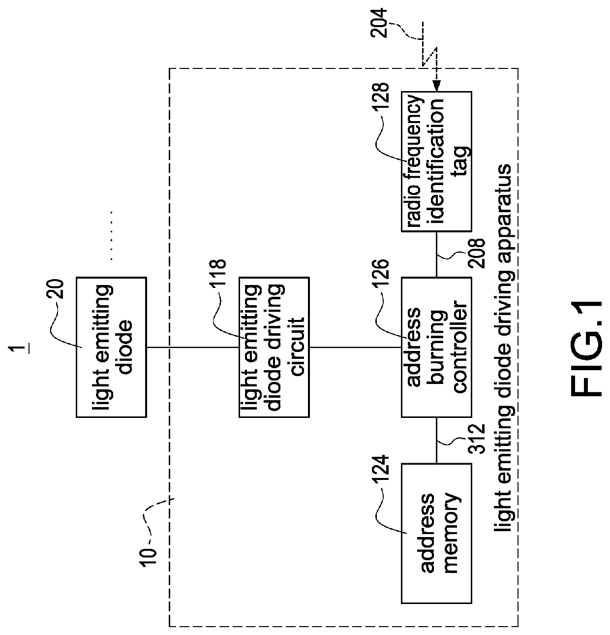
[0047]FIG. 1 shows a block diagram of the light emitting diode lamp utilizing the radio frequency identification signal of the present disclosure. A light emitting diode lamp 1 of the present disclosure comprises a light emitting diode driving apparatus 10 and at least one light emitting diode 20. The light emitting diode driving apparatus 10 comprises a radio frequency identification tag 128, an address burning controller 126, an address memory 124 and a light emitting diode driving circuit 118. The at least one light emitting diode 20 is electrically connected to the light emitting diode driving apparatus 10. The address burning controller 126 is electrically connected to the radio frequency identification tag 128. The address memory 124 is electrically connected to the address burning controller 126. The light emitting diode driving circuit 118 is electrically connected to the at least one light emitting diode 20 and the address burning controller 126. Moreover, in an embodiment ...

second embodiment

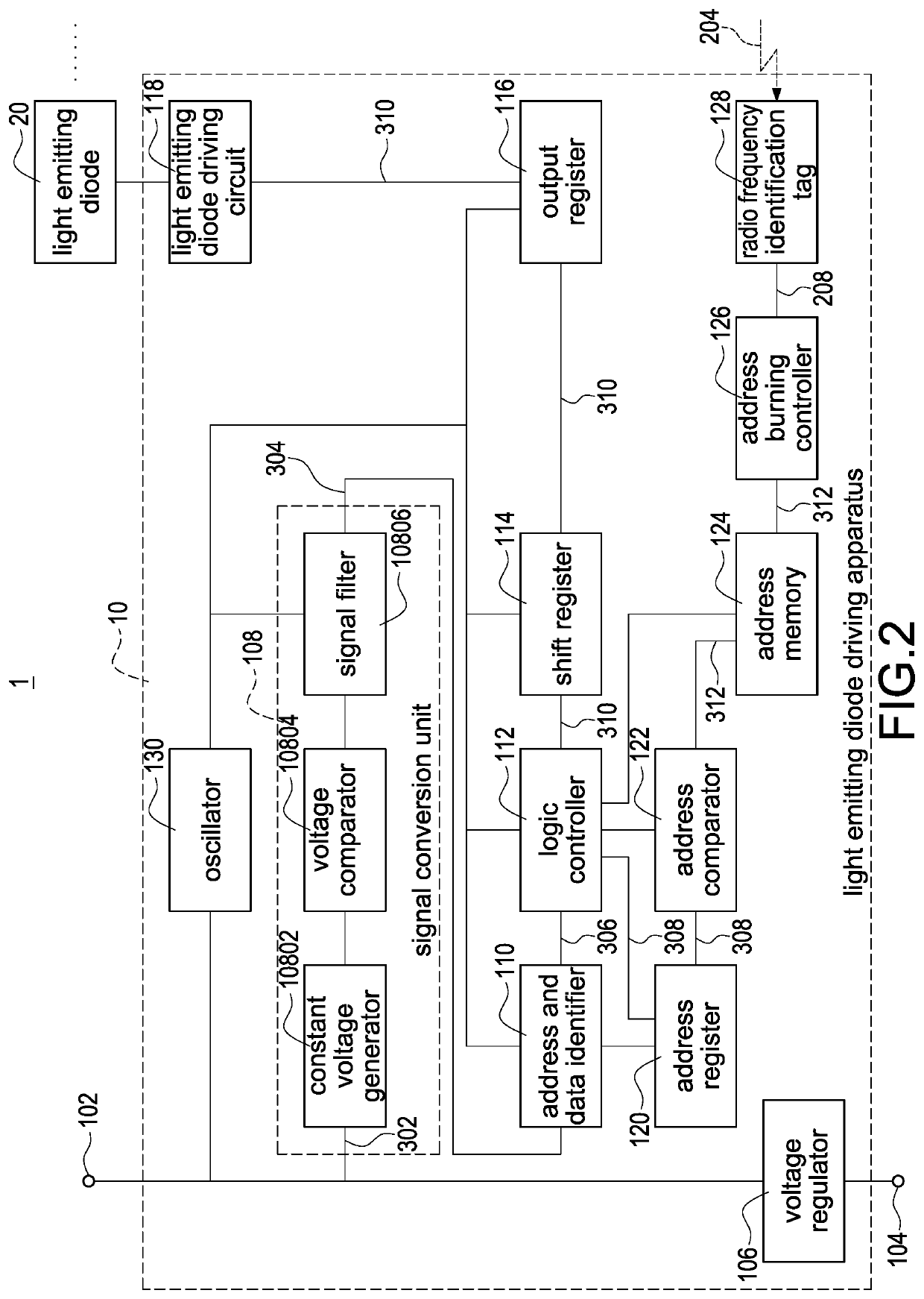
[0051]FIG. 2 shows a block diagram of the light emitting diode lamp utilizing the radio frequency identification signal of the present disclosure. The descriptions of the elements shown in FIG. 2 which are the same as the elements shown in FIG. 1 are not repeated here for brevity. Moreover, the light emitting diode lamp 1 further comprises a first contact 102 and a second contact 104. The light emitting diode driving apparatus 10 further comprises a signal conversion unit 108, an address and data identifier 110, a logic controller 112, a shift register 114, an output register 116, an address register 120, an address comparator 122, a voltage regulator 106 and an oscillator 130. The signal conversion unit 108 comprises a constant voltage generator 10802, a voltage comparator 10804 and a signal filter 10806. Moreover, the voltage comparator 10804 can be replaced by a voltage subtractor.

[0052]The signal conversion unit 108 is electrically connected to the first contact 102. The address...

third embodiment

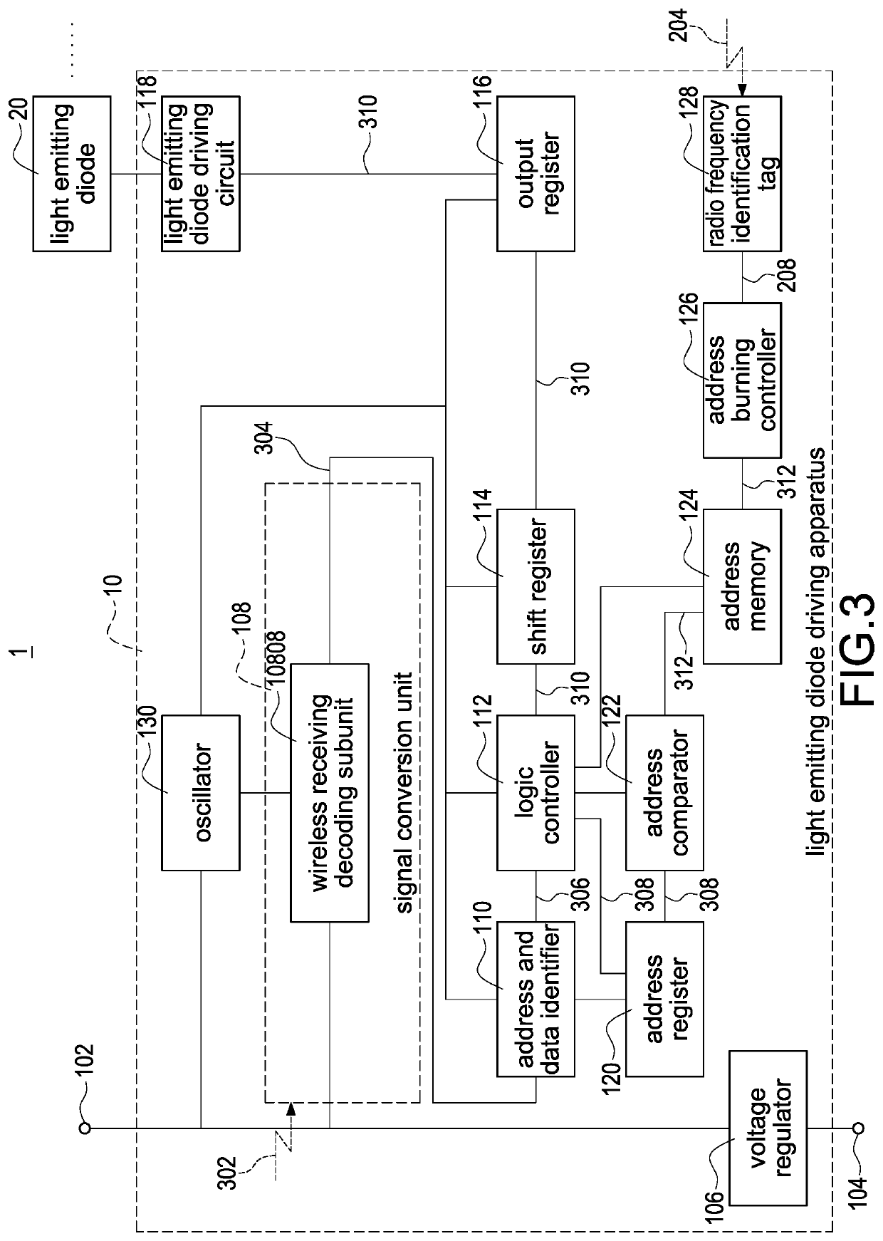
[0055]FIG. 3 shows a block diagram of the light emitting diode lamp utilizing the radio frequency identification signal of the present disclosure. The descriptions of the elements shown in FIG. 3 which are the same as the elements shown in FIG. 2 are not repeated here for brevity. Moreover, the signal conversion unit 108 comprises a wireless receiving decoding subunit 10808. The wireless receiving decoding subunit 10808 is electrically connected to the first contact 102 and the address and data identifier 110. Moreover, the first signal 302 is a wireless signal. The wireless receiving decoding subunit 10808 is configured to decode the first signal 302 to obtain the second signal 304. Moreover, FIG. 3 shows that the present disclosure is in a wireless receiving state that the light emitting diode driving apparatus 10 through the first contact 102 receives only power. The signal conversion unit 108 does not receive the first signal 302 through the first contact 102, but the signal con...


PUM


Abstract

A light emitting diode (LED) lamp includes at least one LED and an LED driver. The LED driver includes at least two terminals, a burning processor, and an address memory. The at least two terminals have a power input terminal and a power output terminal. The power input terminal and the power output terminal are externally coupled to a power line. The burning processor receives a burning activation data of a burning signal through the power input terminal or the power output terminal, and directly and externally receives a burning address data of the burning signal without from the power line. When a burning function of the burning processor is activated by the burning activation data, the burning processor converts the burning address data into a local address data and burns the local address data into the address memory.

Description

CROSS REFERENCE TO RELATED APPLICATION[0001]This application is a Continuation-in-Part of co-pending application Ser. No. 16 / 126,535, filed on Sep. 10, 2018. The entire contents of which are hereby incorporated by reference.BACKGROUND OF THE PRESENT DISCLOSUREField of the Present Disclosure[0002]The present disclosure relates to a light emitting diode (LED) lamp, and especially relates to a light emitting diode (LED) lamp receiving a burning signal including a burning activation data and a burning address data in different manners.Description of the Related Art[0003]Currently, there are two types of the related art light emitting diode lamps: the serial-type light emitting diode lamp and the parallel-type light emitting diode lamp. Both the serial-type light emitting diode lamp and the parallel-type light emitting diode lamp need to use a plurality of power transmission lines and signal transmission lines, which waste wires. Afterwards, the related art technology which transmits the...

Claims


Application Information

Patent Timeline
IPC IPC(8): H05B45/30H05B47/19
CPCH05B45/30H05B47/19
Inventor PENG, WEN-CHI
Owner SEMISILICON TECH
Why Eureka
Try Eureka