Unlock instant, AI-driven research and patent intelligence for your innovation.

Fault detection for microphone array

a microphone array and fault detection technology, applied in the field of microphone arrays, can solve the problems of affecting the communication ability of the device, detect failures, and affecting the ability of the device to detect failures

Active Publication Date: 2019-09-03
MOTOROLA SOLUTIONS INC
View PDF12 Cites 13 Cited by
  • Summary
  • Abstract
  • Description
  • Claims
  • Application Information

AI Technical Summary

Benefits of technology

The patent is about a method and apparatus for detecting faulty microphones in a portable communication device. The invention uses a correlation-based metric between multiple microphones to determine if a microphone has a noisy or "static" failure mode. The approach is robust against windy conditions and has been tested under a wide range of wind conditions. The technical effect of the invention is to provide improved reliability over past faulty microphone detection schemes and minimize false failure detections caused by wind.

Problems solved by technology

Such portable communication devices are often required to operate under robust environmental conditions, including high noise and windy environments.
Traditional energy based failure detectors can be tricked if the microphone failure results in a significantly loud noise or static signal being fed to the audio processing chain.
If not properly managed, such static can impede the device's ability to communicate.
For example, in an audio-video recording device, such static may cause a noisy recording.
Unfortunately, past energy based schemes for detecting a faulty microphone have tended to create false triggers, and wind noise is one such false trigger.
A microphone failure can manifest itself in different forms: no audio at all, the level being very low, or the audio signal being extremely noisy, or any level in between.
Hence, the use of signal power for failure detection makes it difficult to distinguish between a faulty microphone and a working microphone being subjected to wind noise.
If IMM does not have any Gs, then it is in a windy condition.
This aliasing is undesired when trying to derive correlation metrics, therefore the operational frequency range needs to be set with this in mind.

Method used


Image

  • Fault detection for microphone array
  • Fault detection for microphone array
  • Fault detection for microphone array

Examples


Embodiment Construction

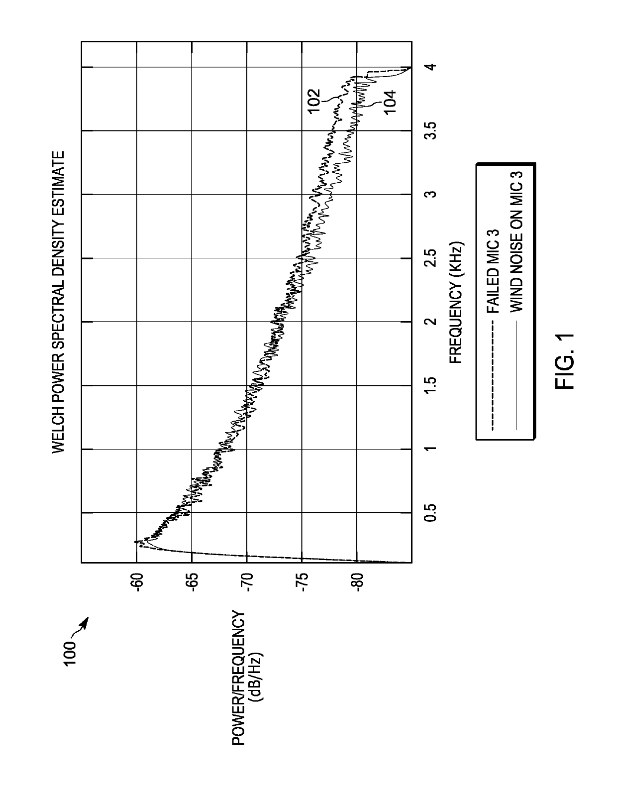
[0014]Briefly, there is provided herein a method and apparatus for detecting a faulty microphone within a microphone array of a portable communication device. A microphone failure can manifest itself in different forms: no audio at all, the level being very low, or the audio signal being extremely noisy, or any level in between. Failure modes may result in a very loud static noise on the microphone signal. FIG. 1 is a graph 100 showing two power spectral densities 102, 104 comparing 30 seconds of audio recording for a portable communication device in which a microphone (mic3) failed 104, as compared to 30 seconds of data for a similar device (having all good microphones mics) in wind 102. Power spectral densities 102, 104 have been normalized for absolute level. As can be seen from the graph 100, the power spectral densities (PDSs) between the faulty microphone 104 and the non-faulty microphone 102 subject to wind noise are very similar. Hence, the use of signal power for failure de...


PUM


Abstract

Reliable detection of a microphone failure along with corrective action are provided for a portable communication device having multiple microphones. The faulty microphone detection uses a correlation based metric between three (3) or more microphones. The approach is based on full cross correlation, including phase as well as magnitude, between unique microphone pairs for isolating a faulty microphone condition. The approach allows for the determination of precisely which microphone has failed and minimizes false triggers under windy conditions within a microphone array.

Description

TECHNICAL FIELD[0001]The present application relates to microphone arrays and more particularly to fault detection for a microphone array of a portable communication device.BACKGROUND[0002]Portable communication devices, particularly those used in public safety applications, may incorporate a microphone array to provide improved audio communication. Such portable communication devices are often required to operate under robust environmental conditions, including high noise and windy environments. There is a need for detecting bad, faulty, or plugged microphone conditions, as such conditions can cause a microphone to go into a state of emitting high levels of static noise. Traditional energy based failure detectors can be tricked if the microphone failure results in a significantly loud noise or static signal being fed to the audio processing chain. If not properly managed, such static can impede the device's ability to communicate. For example, in an audio-video recording device, su...

Claims


Application Information

Patent Timeline
IPC IPC(8): H04R29/00
CPCH04R29/004H04R29/005H04R29/007H04R2410/07
Inventor LANDRON, DANIELFIENBERG, KURT S.
Owner MOTOROLA SOLUTIONS INC