Shock absorbing arrangement configured to withstand impact shock

a technology of shock absorption and shock absorption, which is applied in the direction of waterborne vessel navigational aids, instrumentation, vessel construction, etc., can solve the problems of significant deviation over distance, radar inoperable, and significant impairing accuracy and functionality of radar, so as to alleviate, eliminate, or mitigate one or more of the problems and deficiencies

Active Publication Date: 2019-10-15
SAAB AB
View PDF19 Cites 3 Cited by
  • Summary
  • Abstract
  • Description
  • Claims
  • Application Information

AI Technical Summary

Benefits of technology

[0011]With the above background in mind, then an object of the present disclosure is to provide an improved solution of how to arrange sensitive equipment and devices to structures which may be exposed to high acceleration forces or impact shocks, particularly to provide an improved shock absorbing arrangement applicable e.g. for radar antenna turntables. The present disclosure seeks to mitigate, alleviate, or eliminate one or more of the problems and deficiencies with current solutions.

Problems solved by technology

Even the smallest dislocation of a radar antenna from a presumed fix position will cause a significant deviation over distance and impair accuracy and functionality of the radar significantly, in worst case making the radar inoperable.
Failure of the radar functionality of e.g. a warship might have disastrous consequences.
This may be a problem e.g. for ship installed equipment where extremely rough sea and deliberate or unintentional mine detonations exposes such equipment for extremely high acceleration force, herein referred to as impact shock.
Such impact shock may affect mechanical installations and thereby dislocate devices or equipment.
Current impact shock absorbing solutions often use complex systems relying on e.g. delicate hydraulic or pneumatic solutions and complex control algorithms.
Such solutions are often costly, add significant weight and / or are bulky and are often not sufficiently robust for the rough conditions such installations may be exposed to.

Method used


Image

  • Shock absorbing arrangement configured to withstand impact shock
  • Shock absorbing arrangement configured to withstand impact shock
  • Shock absorbing arrangement configured to withstand impact shock

Examples


Embodiment Construction

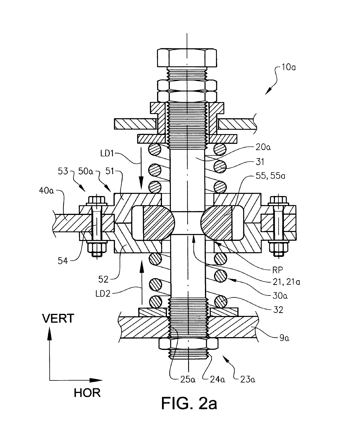
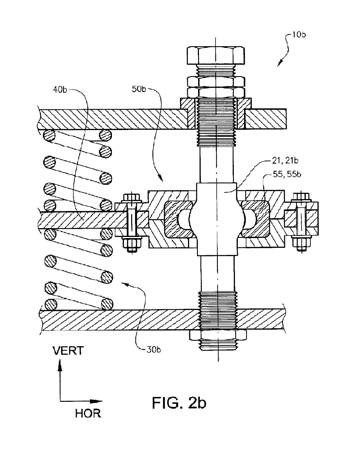
[0046]The following description of example embodiments of the invention provided is presented only for purposes of illustration and should not be seen as limiting. The description is not intended to be exhaustive and modifications and variations are possible in light of the above teachings or may be acquired from practice of various alternatives to the provided embodiments. The examples discussed herein were chosen and described in order to explain the principles and the nature of various example embodiments and its practical application to enable one skilled in the art to utilize the example embodiments in various manners and with various modifications as are suited to the particular use contemplated. It should be appreciated that the embodiments presented herein separately may be practiced in any combination with each other. In FIG. 2a to FIG. 4b a vertical VERT and a horizontal HOR direction is indicated by VERT and HOR arrows.

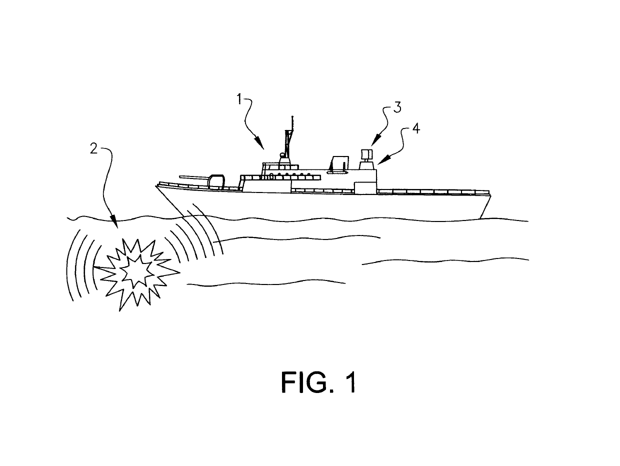
[0047]FIG. 1 discloses a schematic view of a ship 3 e...


PUM


Abstract

The present disclosure relates to a shock absorbing arrangement suitable e.g. for ship installed structures comprising a rod, a resilient member arranged in connection to the rod, a structure element and a locking member arranged in connection to the structure element. The locking member is arranged to detachably lock the structure element at a resting position at the rod and the locking member, or the structure element, is supported by the resilient member. The resilient member is configured such that a spring force of the resilient member acts to maintain the structure element essentially at the resting position at the rod. The locking member is further configured to release the structure element from the resting position when being exposed to a force exceeding a predetermined holding force, whereupon the resilient member acts to reinstate the locking of the structure element at the resting position at the rod. The present disclosure further relates to a shock absorbing structure comprising such shock absorbing arrangements.

Description

CROSS REFERENCE TO RELATED APPLICATIONS[0001]This application is a National Stage Application, filed under 35 U.S.C. § 371, of International Application No. PCT / SE2015 / 051355, filed Dec. 16, 2015; the contents of which are hereby incorporated by reference in their entirety.BACKGROUND[0002]Related Field[0003]The present disclosure refers to a shock absorbing arrangement configured to withstand impact shock. The shock absorbing arrangement may e.g. be applied in order to protect sensitive, ship installed equipment such as radar antennas from impact shock caused by mine detonations at sea. Although the shock absorbing arrangement will be described with respect to a ship installed radar antenna, the disclosure is not restricted to this particular implementation but may also be used in other applications where protection of sensitive devices against impact shock or like is required. The present invention further relates to a shock absorbing structure comprising such shock absorbing arran...

Claims


Application Information

Patent Timeline
Patent Type & Authority Patents(United States)
IPC IPC(8): F16F3/00B63B17/00B63B3/10F16F15/04F16F3/02F16F3/04F16F15/067B63G9/00
CPCB63B3/10B63G9/00F16F15/067F16F3/04F16F2230/0041B63B49/00G01S7/03H01Q1/002H01Q1/18H01Q1/34H01Q3/04B63B17/0081F16F3/02F16F15/04
Inventor NORRMAN, BERNT
Owner SAAB AB
Why Eureka
Try Eureka