

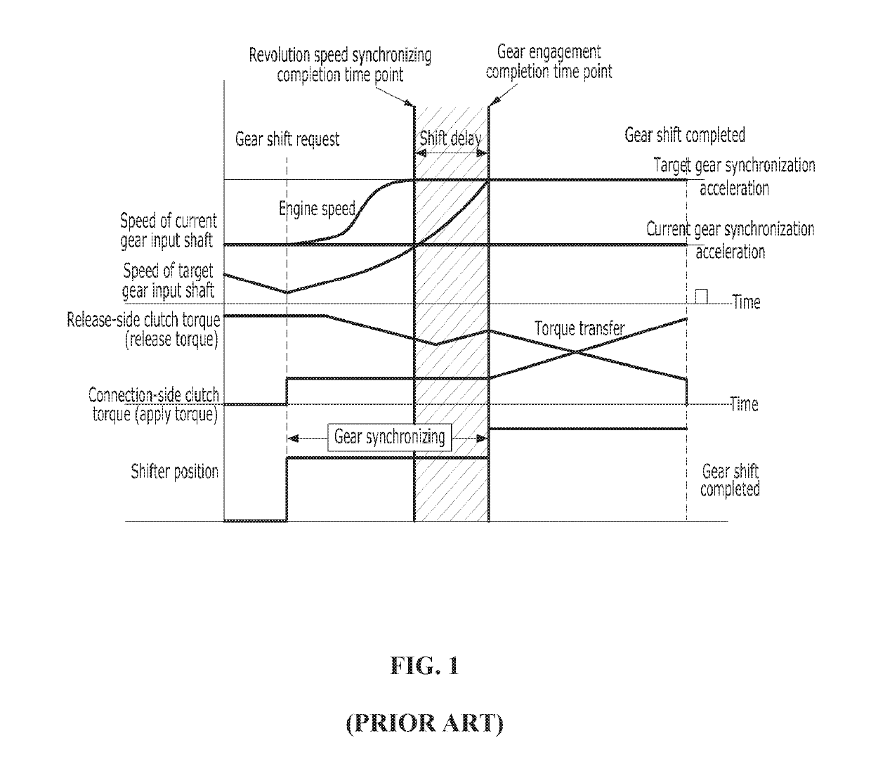
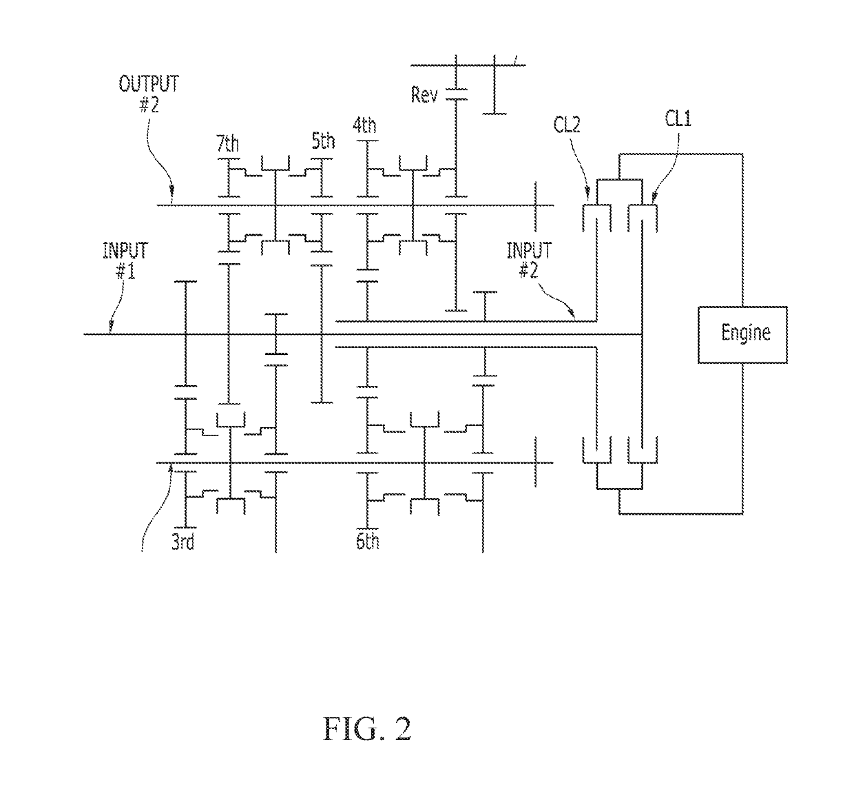
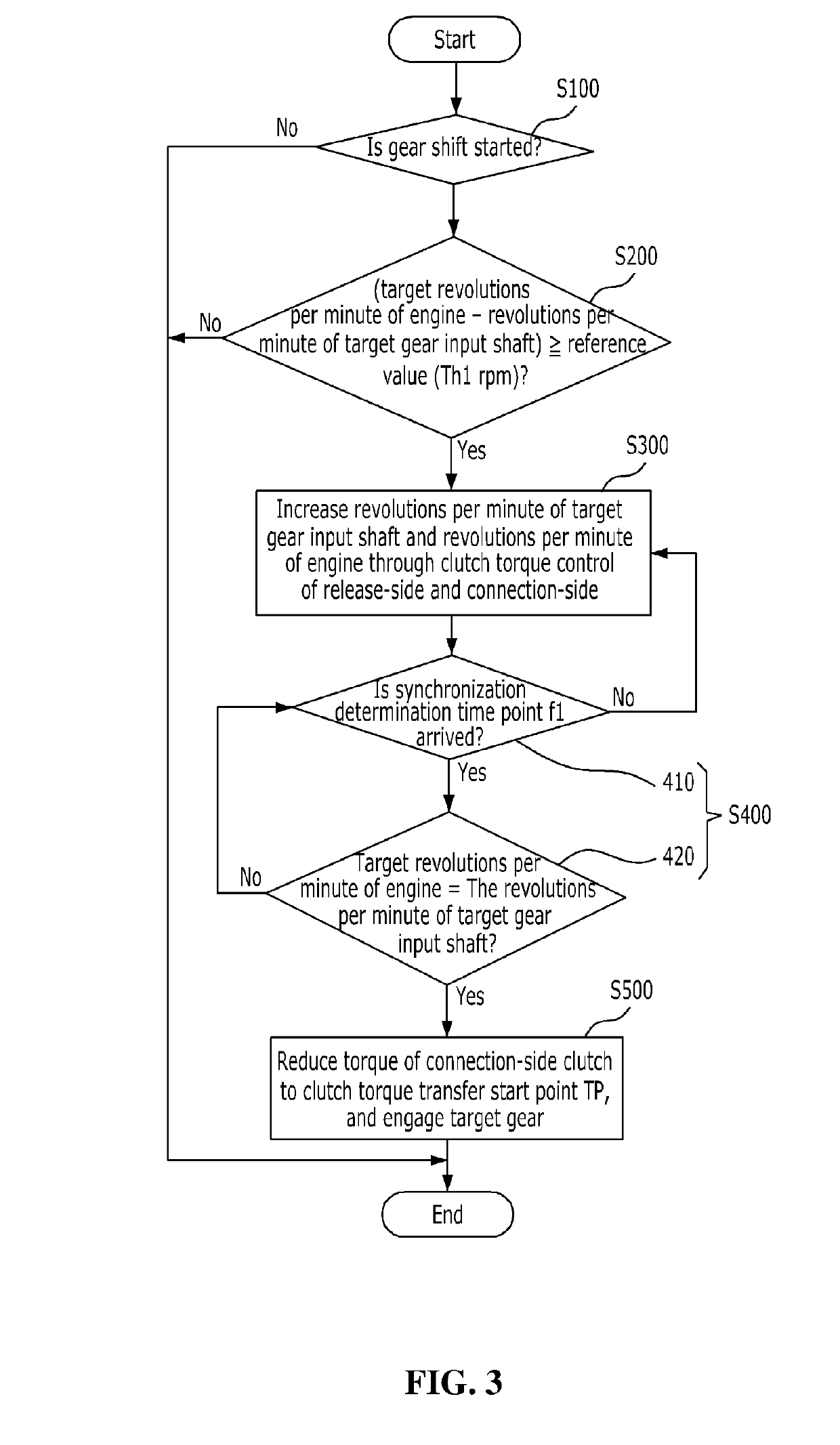
Gear shift control method of DCT vehicle
a technology of gear shift control and dct vehicle, which is applied in the direction of mechanical equipment, driver input parameters, transportation and packaging, etc., can solve the problems of reducing the quality of gear shift, affecting the transmission of torque, and the driver may feel that the torque is not properly transferred, so as to minimize the feeling of discontinuity and abrasion of the clutch
- Summary
- Abstract
- Description
- Claims
- Application Information
AI Technical Summary
Benefits of technology
Problems solved by technology
Method used
Image

Examples
Embodiment Construction
[0037]The preferred embodiments of the invention will be hereafter described in detail, with reference to the accompanying drawings.
[0038]The terms used in the specification are used to describe only specific embodiments and are not intended to limit the present disclosure. Singular forms are intended to include plural forms unless the context clearly indicates otherwise. It will be further understood that the terms “include”, “comprise” and “have” used in this specification specify the presence of stated features, numerals, steps, operations, components, parts or a combination thereof, but do not preclude the presence or addition of one or more other features, numerals, steps, operations, components, parts or a combination thereof.
[0039]The terms such as “first” and “second” can be used in describing various elements, but the above elements shall not be restricted by the above terms. The above terms are used only to distinguish one element from the others.
[0040]In addition, the ter...
PUM
 Abstract
Description
Claims
Application Information