Lift and pallet

a technology which is applied in the field of lift and pallet, can solve the problems of inability to use in some applications, and the narrowness of walk-in coolers for the larger pallet li

Active Publication Date: 2019-11-19
REHRIG PACIFIC CO INC
View PDF164 Cites 9 Cited by
  • Summary
  • Abstract
  • Description
  • Claims
  • Application Information

AI Technical Summary

Problems solved by technology

Larger lifts can be used to move more pallets at one time; however, these cannot be used in some applications.
In some stores, the aisles are narrow and / or the walk-in coolers are too narrow for the larger pallet lifts.

Method used


Image

  • Lift and pallet
  • Lift and pallet
  • Lift and pallet

Examples


Embodiment Construction

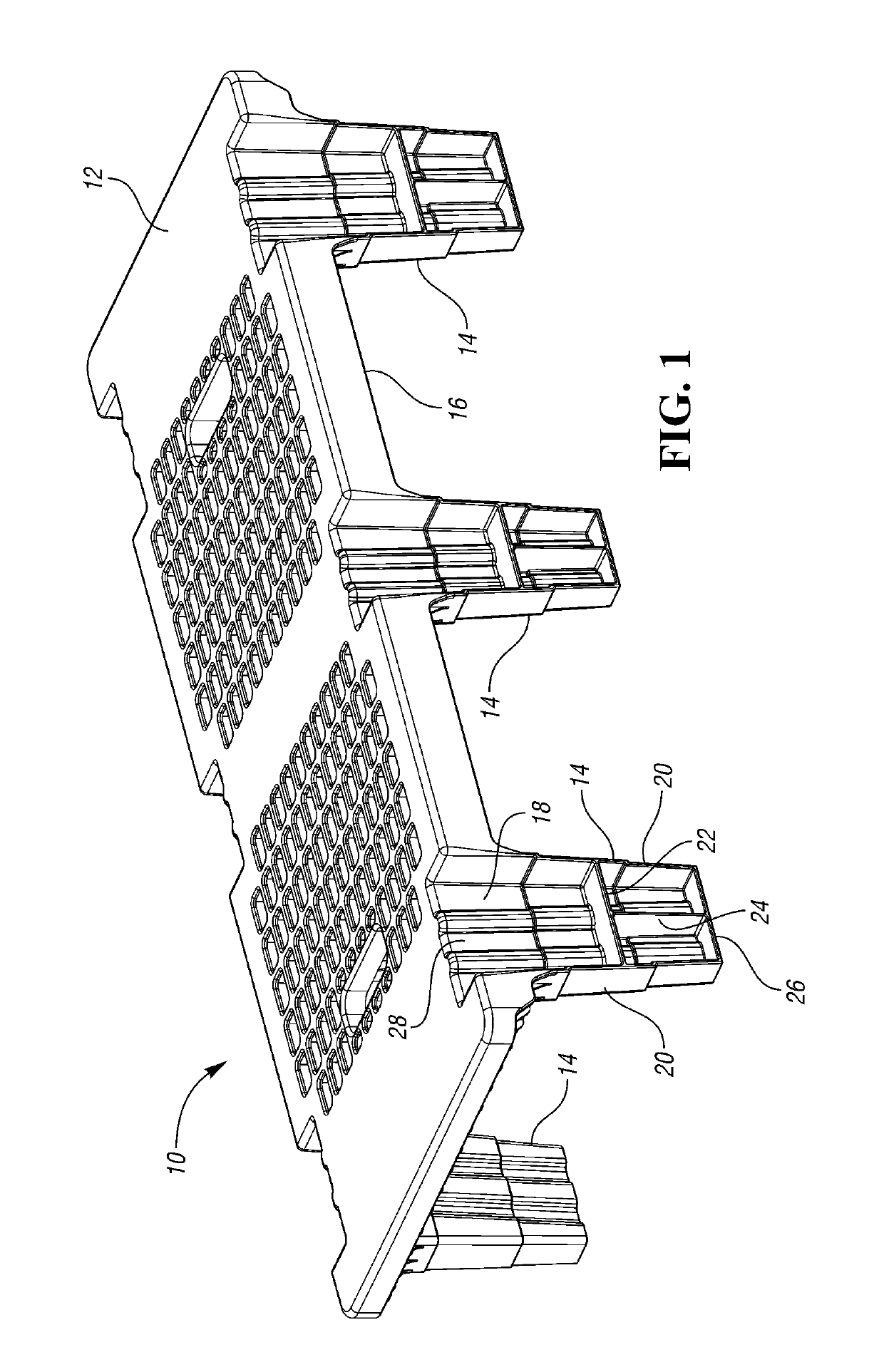
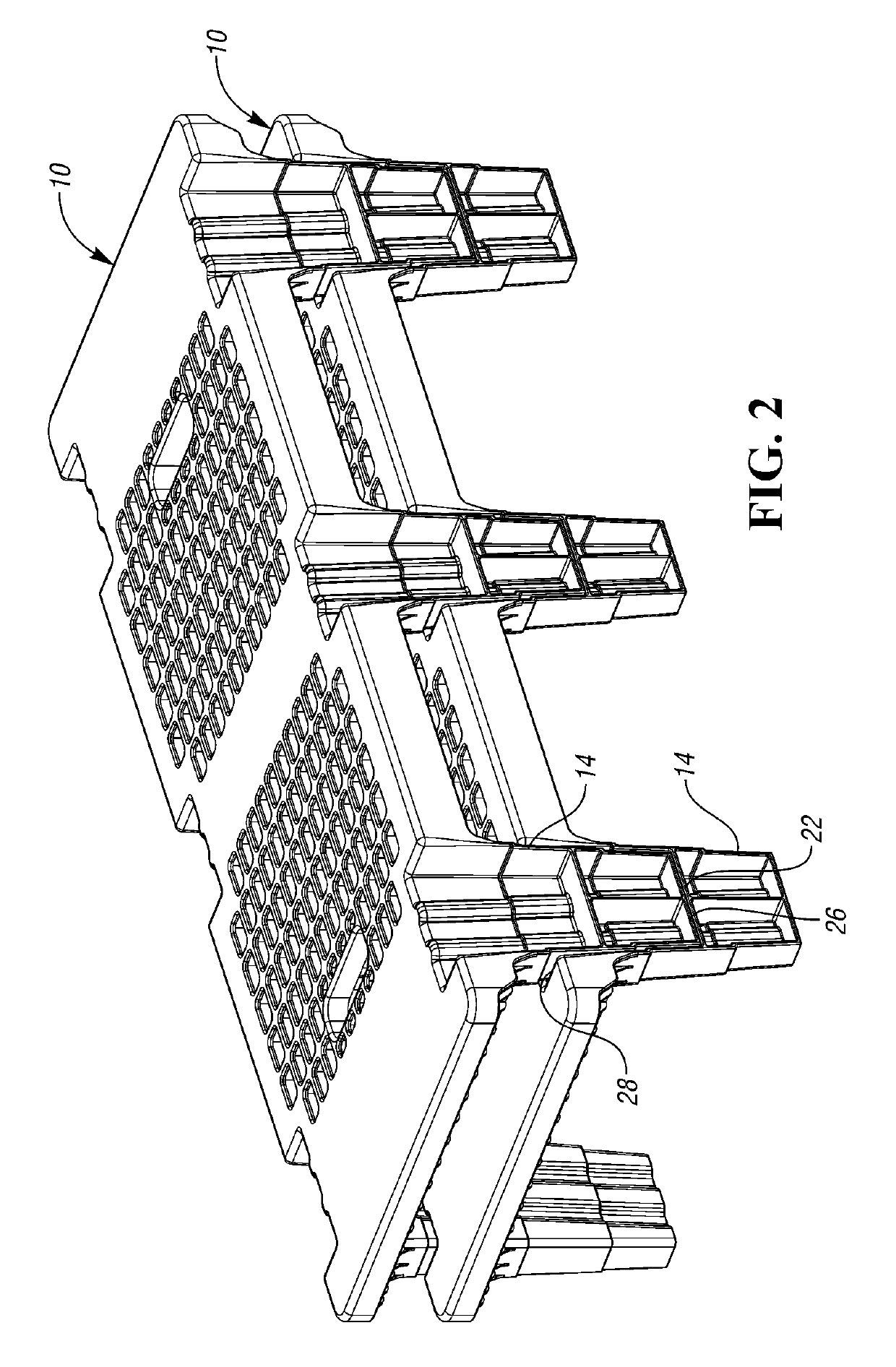
[0037]A pallet 10 is shown in FIG. 1. The pallet 10 is an injection molded plastic pallet 10 having a deck 12 supported above the floor by a plurality of feet 14. The deck 12 includes a plurality of ribs for reinforcement and a lip 16 extending about the periphery. The pallet 10 is “half pallet” size, such as 18″×48″, 20″×48″, 29″×42″.

[0038]The feet 14 are hollow and are U-shaped in cross-section, opening outward. This reduces the footprint of the pallet 10, but optionally, the feet 14 could have an outer wall enclosing the feet 14. The feet 14 each include an inner wall 18, which may be corrugated as shown, for strength. The feet 14 each include opposed side walls 20 and a bottom wall 26. A horizontal reinforcing wall 22 connects the inner wall 18 and side walls 20 and is spaced above the bottom wall 26. A vertical reinforcing wall 24 extends vertically from the bottom wall 26 to the horizontal reinforcing wall 22. The deck 12 has an opening 28 aligned with each foot 14, leading in...


PUM


Abstract

A pallet lift includes a pair of outer tines movable between an expanded position spaced outward away from inner tines and a retracted position adjacent the inner tines. The inner and outer tines are supported by wheels at locations spaced away from the lift mechanism. A pallet includes a plurality of nestable feet that open outwardly of the pallet to reduce the footprint. A second pallet includes a side wall extending downward from side edges of the pallet to define an opening adjacent outer feet.

Description

BACKGROUND[0001]Pallet lifts are used to move pallets loaded with goods around a warehouse or store. Larger lifts can be used to move more pallets at one time; however, these cannot be used in some applications. In some stores, the aisles are narrow and / or the walk-in coolers are too narrow for the larger pallet lifts.SUMMARY[0002]A first pallet lift includes a lift mechanism and at least one inner tine secured to the lift mechanism. At least one wheel supports the inner tines and is spaced away from the lift mechanism along a longitundinal axis of the inner tines. A pair of outer tines are secured to the lift mechanism and positioned outward of the inner tines. The pair of outer tines are movable between an expanded position spaced outward away from the inner tines and a retracted position adjacent the inner tines. The outer tines may also be supported by at least one wheel positioned away from the lift mechanism. Thus, the pallet may be used to support more than one pallet in the ...

Claims


Application Information

Patent Timeline
Patent Type & Authority Patents(United States)
IPC IPC(8): B65D19/00B66F9/065B66F9/14
CPCB66F9/065B66F9/143B65D19/0018B65D2519/00034B65D2519/00796B65D2519/00069B65D2519/00407B65D2519/00268B65D2519/00318B65D2519/00467B65D2519/00308B65D2519/00338B65D2519/0094B65D2519/00288B65D2519/00472B65D2519/00771B62B3/0612B62B2203/24
Inventor KING, PHILIP A.HASSELL, JON P.APPS, WILLIAM P.KALINOWSKI, DANE GIN MUN
Owner REHRIG PACIFIC CO INC
Why Eureka
Try Eureka