Simply safe ladder clamp

a ladder clamp and simple technology, applied in the field of safety, can solve the problems of putting the ladder climber at risk for life and limbs

Active Publication Date: 2019-12-03
FORT MARC
View PDF10 Cites 0 Cited by
  • Summary
  • Abstract
  • Description
  • Claims
  • Application Information

AI Technical Summary

Benefits of technology

[0001]The present invention is directed to the field of safety. More particularly, ...

Problems solved by technology

Numerous attempts have been made to produce a ladder clamp which prevents a ladder from s...

Method used


Image

  • Simply safe ladder clamp
  • Simply safe ladder clamp
  • Simply safe ladder clamp

Examples


Embodiment Construction

)

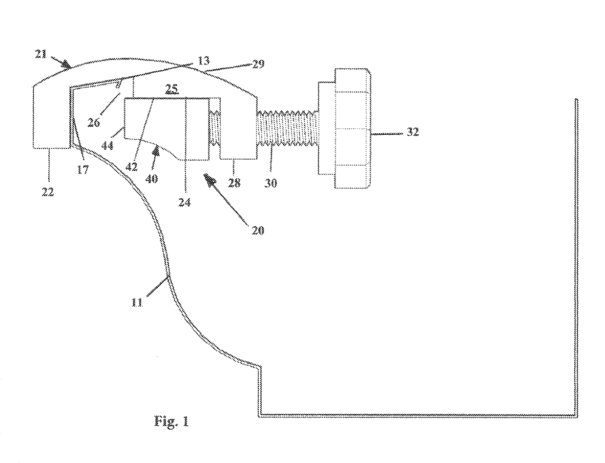
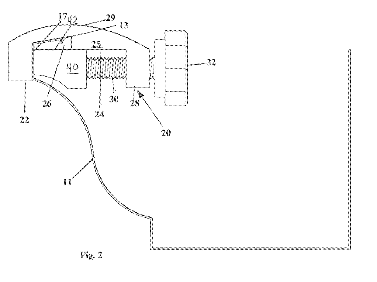
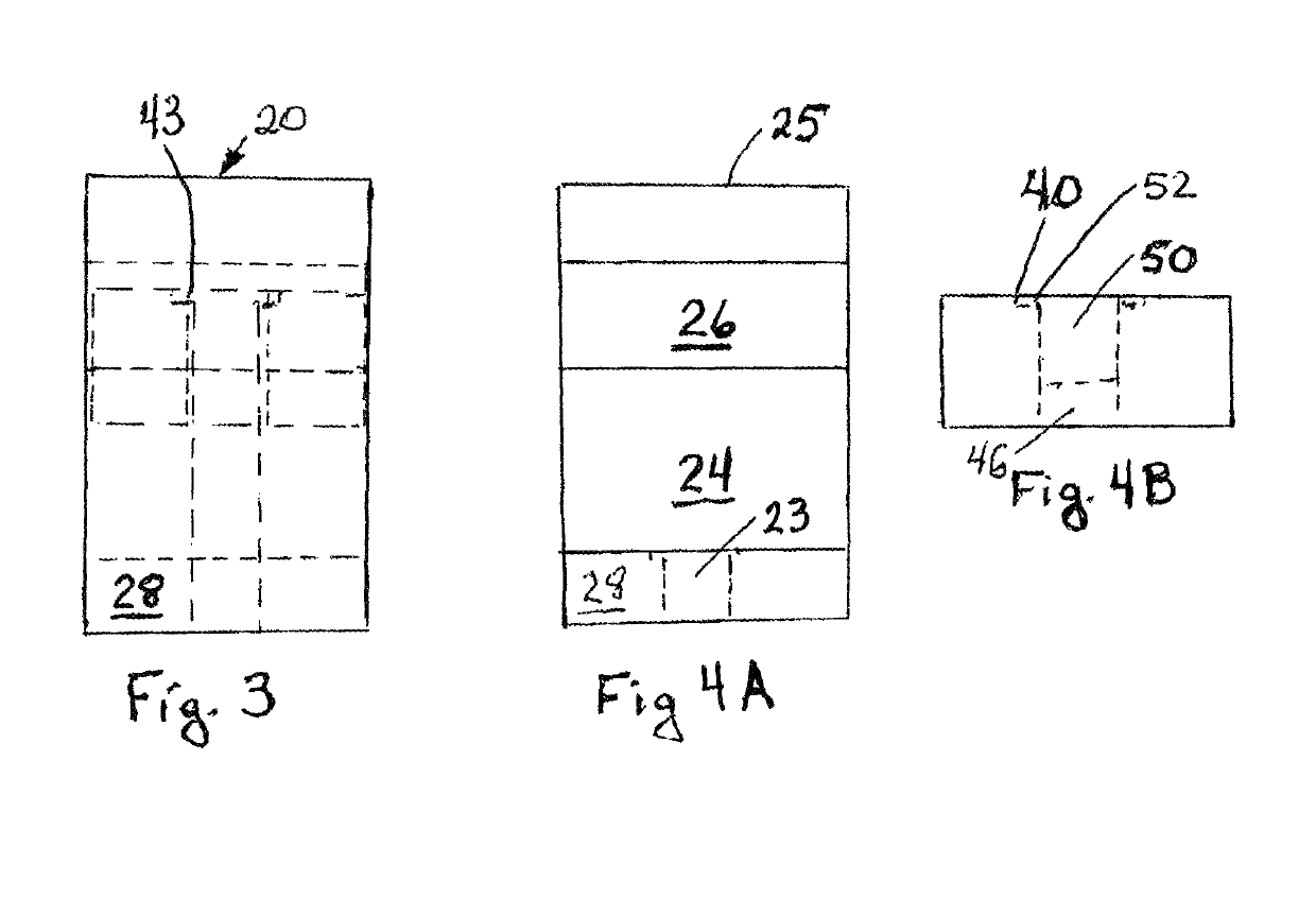
[0012]A first embodiment of the simply safe ladder clamp of the present invention is depicted in FIGS. 1-3 generally at 20. Simply safe ladder clamp 20 comprises a first generally Sigma-shaped body portion 21 (the E is rotated 90° clockwise in FIGS. 1 and 2) having a first downwardly extending arm 22 and a second downwardly extending arm 28 which together subtend and define an intermediate element 25 with an inner laterally extending flat surface 24 and a recess 26 adjacent the first downwardly extending arm 28. Recess 26 is formed to accommodate the inwardly protruding flange 13 of gutter 11.

[0013]A clamping member 40 has a first flat face 42 for engaging the laterally extending surface of intermediate element 25 of body portion 21 and a second orthogonal flat face 44 for engaging an inner surface of the vertical face 17 of the gutter 11 opposite first downwardly extending arm 22 to clamp said simply safe ladder clamp 20 to the vertical face 17 of the gutter 11. An elongated threa...


PUM


Abstract

A simply safe ladder clamp includes a first generally Sigma-shaped body portion having a first downwardly extending arm 2 and a second downwardly extending arm which together subtend and define an intermediate element with an inner laterally extending flat surface and a recess adjacent the first downwardly extending arm. A clamping member captures a flat portion of the gutter between the flat portion and an inner surface of the first downwardly extending arm to mount the simply safe ladder clamp to the gutter. Preferably two simply safe ladder clamps are used, positioned inside the legs of a ladder to prevent movement of the ladder relative to the gutter.

Description

BACKGROUND AND SUMMARY OF THE INVENTION[0001]The present invention is directed to the field of safety. More particularly, the present invention is directed to an elegantly simple ladder clamp that is simply safe.[0002]Numerous attempts have been made to produce a ladder clamp which prevents a ladder from sliding along the face of a gutter thereby putting the ladder climber at risk for life and limb. Applicant's earlier invention, Ladder-Supporting Gutter Clamping System, U.S. patent application Ser. No. 15 / 916,507 filed Mar. 9, 2018, goes a long way toward providing a simplified, effective ladder clamp. However, the present invention takes an additional step at providing simple, effective ladder clamps that can be produced inexpensively without jeopardizing effectiveness resulting in a clamp that is truly, simply safe.[0003]The present invention is a simply safe ladder clamp for gutters having a front face with a portion which has a generally vertical face with an inwardly protrudin...

Claims


Application Information

Patent Timeline
IPC IPC(8): E06C7/48
CPCE06C7/486
Inventor FORT, MARC
Owner FORT MARC
Why Eureka
Try Eureka