Data compression

a data compression and data technology, applied in the field of data compression, can solve the problems of higher data compression, increased data quality degradation, and increased cost of harsher quantisation

Inactive Publication Date: 2009-02-10
SONY UK LTD
View PDF8 Cites 0 Cited by
  • Summary
  • Abstract
  • Description
  • Claims
  • Application Information

AI Technical Summary

Benefits of technology

[0015]The invention provides an elegantly simple and convenient way of detecting previous quantisation parameters used in data which is presented to the apparatus in an uncompressed form. Rounding effects of previous quantisation operations are detected. A corollary of this is that a detection can be made as to whether the data has previously been compressed or not.

Problems solved by technology

Larger quantisation divisors result in higher compression of data at the expense of harsher quantisation.
Harsher quantisation results in greater degradation in the quality of the reproduced image.
Although selecting the least harsh quantisation will result in the best possible image quality (i.e. the least noisy image) on reproduction for “source” image data that has not undergone one or more previous compression / decompression cycles, it has been established that this is not necessarily the case for “non-source” image data.
Thus for non-source input image data the quantisation divisor having the smallest possible magnitude that meets a required data rate will not necessarily give the best reproduced image quality.
This results in poor multi-generation stability of the quantisation divisors which ultimately results in reduced quality of the reproduced image quality for the 2nd and higher generation images.
Furthermore since the value of DCT—PRECISION is fixed prior to performing the series of trial quantisations a poor choice of DCT—PRECISION cannot be changed dynamically during the later part of the encoding process.

Method used


Image

  • Data compression
  • Data compression
  • Data compression

Examples


first embodiment

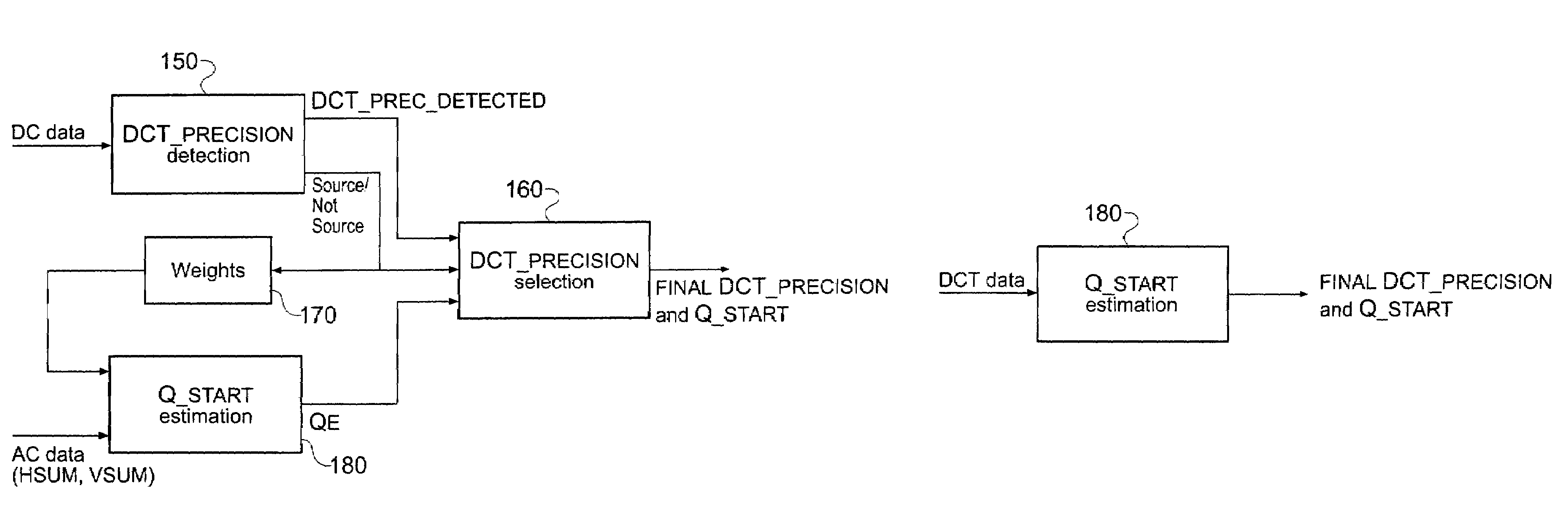
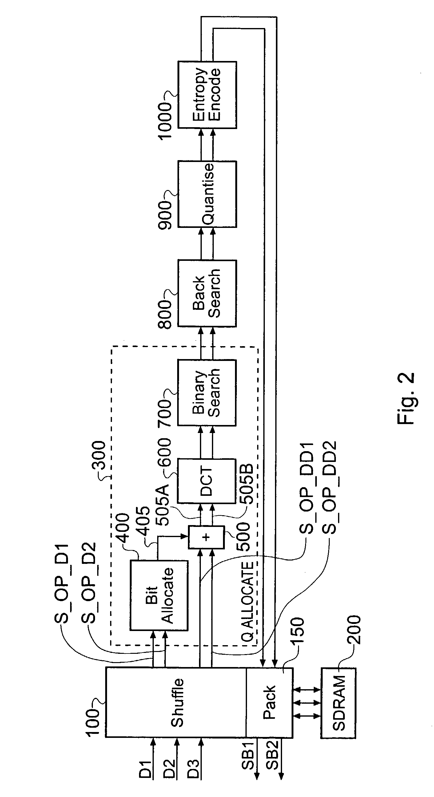
[0047]FIG. 5A schematically illustrates a parameter estimation circuit according to the invention. This parameter estimation circuit is implemented in the shuffle module 100 of the encoder of FIG. 2. The parameter estimation circuit comprises a DCT—PRECISION detection module 150, a DCT—PRECISION selection module 160, a weights module 170 and a Q—START estimation module 180.

[0048]As explained above the DCT—PRECISION index, which is used in quantising all of the DCT coefficients, has four possible values 0, 1, 2, 3 and is specified on a frame by frame basis. The value DCT—SCALER≡2DCT—PRECISION is the quantisation divisor associated with DCT—PRECISION. During the encoding process it is important to correctly determine the DCT—PRECISION index. Furthermore it is necessary to provide a Q—SCALE estimate. Q—START is an estimate of the ideal Q—SCALE for the field or frame at the chosen DCT—PRECISION and is used as a reference scale for the lowest resolution trial quantisations performed by t...

second embodiment

[0089]FIG. 5B schematically illustrates a parameter estimation circuit according to the invention. The parameter estimation circuit of FIG. 5B comprises a Q—START estimation module 180 which is identical in structure and function to the corresponding module in the parameter estimation circuit of FIG. 5A described above. In this embodiment of the invention both the value of the parameter Q—START and the final value for DCT—PRECISION are estimated from the numerical value of QE in accordance with either Table 1 for activity off mode or Table 2 for activity on mode. Note that since the estimated values of Q—START and DCT—PRECISION produced by the parameter estimation circuit of FIG. 5B do not take account of “jitter” the estimates produced by the parameter estimation circuit of FIG. 5A are likely to be more accurate.


PUM


Abstract

A data compression apparatus for performing data compression on input data comprises a quantisation parameter estimation arrangement for deriving an estimated value of a quantisation parameter used in a previous compression / decompression cycle applied to the input data, by detecting rounding effects in data values of at least a subset of the input data; and a parameter selection arrangement, responsive to the quantisation parameter estimation arrangement for selecting a quantisation parameter for use in compression of the input data.

Description

BACKGROUND OF THE INVENTION[0001]1. Field of the Invention[0002]The present invention relates to data compression.[0003]2. Description of the Prior Art[0004]Data compression techniques are used extensively in the data communications field in order to communicate data at bit rates that can be supported by communication channels having dynamically changing but limited bandwidths. Image data is typically compressed prior to either transmission or storage on an appropriate storage medium and it is decompressed prior to image reproduction.[0005]In the case of still images data compression techniques take advantage of spatial redundancy, whilst for moving images both spatial and temporal redundancy is exploited. Temporal redundancy arises in moving images where successive images in a temporal sequence, particularly images belonging to the same scene, can be very similar. The Motion Picture Experts Group (MPEG) has defined international standards for video compression encoding for entertai...

Claims


Application Information

Patent Timeline
IPC IPC(8): G06F15/16G06T9/00H03M7/30H03M7/36H04N1/41H04N7/26H04N7/30
CPCH04N19/197H04N19/46H04N19/196H04N19/60H04N19/126H04N19/40H04N19/88
Inventor PORTER, ROBERT MARK STEFANSAUNDERS, NICHOLAS IANBURNS, JAMES EDWARDLIVING, JONATHAN
Owner SONY UK LTD
Why Eureka
Try Eureka