Raman spectroscopy for minerals identification

a technology of raman spectroscopy and minerals, applied in the field oframan spectroscopy, can solve the problems of high process cost, inability to widely deploy to or readily available to a high percentage of individuals/institutions, and large sample preparation requirements, and continue to require considerable training and experien

Active Publication Date: 2020-05-26
BARTHOLOMEW PAUL
View PDF14 Cites 0 Cited by
  • Summary
  • Abstract
  • Description
  • Claims
  • Application Information

AI Technical Summary

Benefits of technology

[0029]In some embodiments, the apparatus also includes a second set of one or more optical and / or electronic components for reducing sample-heating by the laser beam.
[0033]In some embodiments, the apparatus also includes a second set of one or more optical and / or electronic components for reducing sample-heating by the laser beam.
[0037]In some embodiments the kit also includes a second set of one or more optical and / or electronic components for reducing sample-heating by the laser beam.

Problems solved by technology

However, when an analytical process is highly expensive, requires high amounts of physical space and / or physical support, requires high levels of maintenance and calibration, and / or requires a high level of education and training to operate, it is also impractical—it cannot be widely deployed to or readily available to a high percentage of those individuals / institutions who routinely need analytical results.
The next level of technology traditionally employed is polarized light microscopy, however, this requires considerable sample preparation and continues to require considerable training and experience.
This type and amount of sample preparation means that PXRD requires a sample-preparation delay before each analysis and is extremely difficult-to-impossible to apply to small mineral grains or mineral grains in situ (without extraction).
Additionally, despite the reduction in instrument size that has been achieved for PXRD, it continues to be impractical to attempt to employ PXRD out into a field investigation environment.
However, a general lack of optimization of the Raman technology for application to minerals (and man-made crystalline solids as well) has prevented widespread adoption of Raman technology for RMI.
The performance challenges of Raman technology often intersect or even compete with one another resulting in performance trade-offs.
The central performance challenges are the minimum Raman shift, spectral resolution, spectral range, signal sensitivity, and reducing / avoiding fluorescence interference.
The technology required to increase spectral range generally reduces resolution.
Again, there are technical trade-offs between sensitivity and other performance factors.
The technology employed to increase resolution often reduces signal throughput.
The signal-gathering optics can also be a limiting factor, especially fiber-optics that capture a very low solid angle of light from the sample.
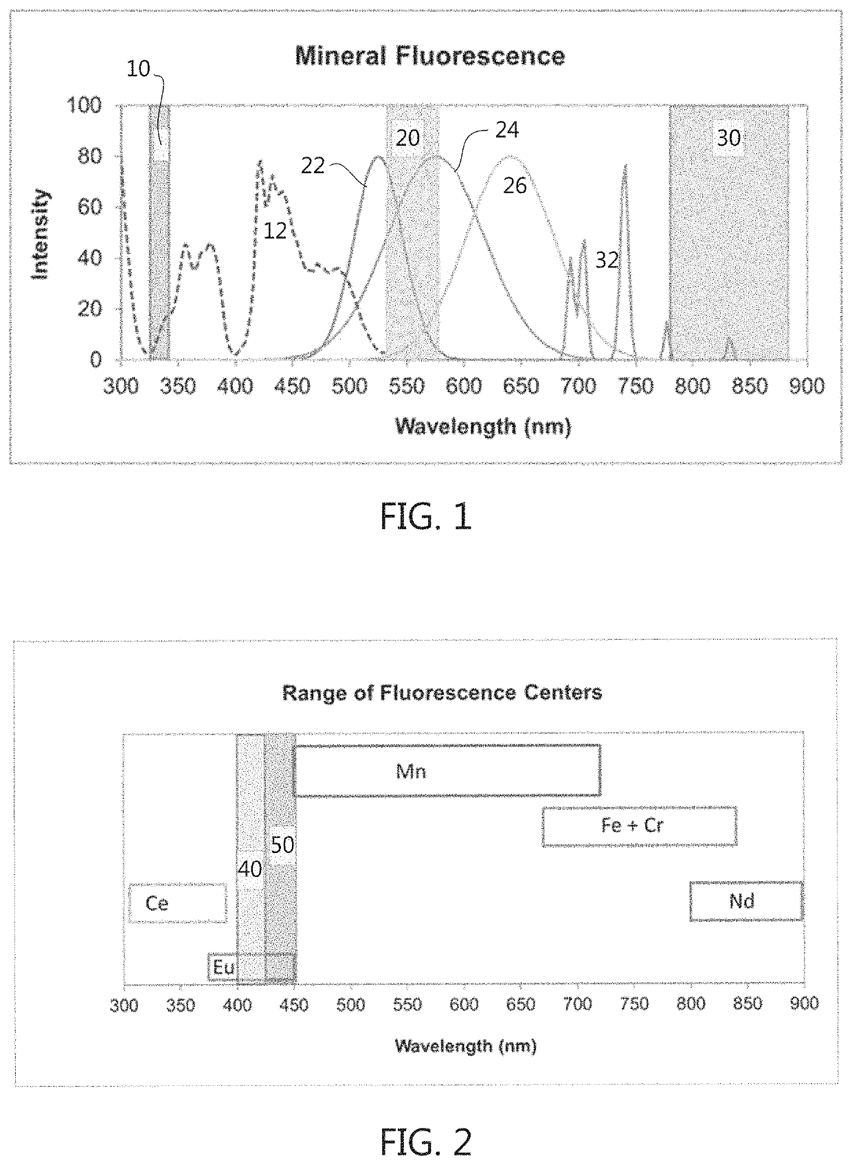
Many sample substances do not respond to the laser light with fluorescence emission, however, when fluorescence light is emitted from the sample it is often so much more intense than the Raman response that the Raman spectrum of the sample cannot be observed at all.
The limitations of this approach for PRMI are expense and complexity.
Employing even two lasers requires much more training and experience to operate and typically results in a Raman system that costs 50% to 90% more than the same model configured with only one laser.
Raman systems with 4 and 5 lasers require considerable space, cost, and maintenance.
The limitations of this approach for PRMI are spectral artifacts and breadth of application.
In addition, the greatest limitation is probably the fact that shifted-excitation is ineffective for samples producing fluorescence orders of magnitude brighter than Raman intensities.
The limitations of this approach for PRMI are expense and sensitivity.
Until recently all gated-Raman systems were expensive and complex custom-made optical-bench systems.
Such a system may have to collect data for an impractical period of time for the many minerals that are weak Raman scatterers.
The primary limitation of this approach for PRMI is sensitivity.
Since many minerals are weak Raman scatterers, the IR laser Raman system has limited application to minerals as a whole.
UV lasers: Raman systems employing UV lasers are relatively rare due to their spectral performance challenges and expense.
A UV Raman system has to examine a narrow spectral region, making it technologically difficult to achieve adequate spectral resolution and the minimum Raman shift of such systems is typically 350 to 450 nm.
The limitations of UV Raman for PRMI are expense and performance.
The components required to meet the performance challenges in the UV are expensive and many, many minerals have important Raman peaks at Raman shifts below 400 nm.
The limitations of Anti-Stokes Raman include shorter wavelength fluorescence and Raman intensity limitations.
However, this becomes physically and technologically impractical for Raman systems using a shorter wavelength laser source partially due to the physical size of the spectrograph component required to achieve useful spectral resolution.
One challenge for a portable / field Raman system is to provide for laser light delivery, signal light collection, and sample visibility for aiming through a single optical port.
Many hand-held units and some portables do not even try to provide for optical analysis aiming and depend upon the analysis site being large enough to simply point the optical front end of the analyzer at it.

Method used


Image

  • Raman spectroscopy for minerals identification
  • Raman spectroscopy for minerals identification
  • Raman spectroscopy for minerals identification

Examples


Embodiment Construction

[0055]Referring now to the drawings, wherein like reference numerals designate corresponding structures throughout the views. The following examples are presented to further illustrate and explain the present invention and should not be taken as limiting in any regard.

[0056]FIG. 1 is a chart representing the characteristics of mineral fluorescence. Peaks 22, 24, and 26 are Mn2+ fluorescence peaks for willemite, hardysonite, and rhodonite, respectively. The group of sharper peaks 32 are Sm2+ fluorescence peaks for anhydrite. The dashed curve 12 is the excitation spectrum for the willemite Mn2+ fluorescence 22 showing what source wavelengths produce higher or lower intensity fluorescence. The bands of the spectrum 10, 20, and 30 show what portion of the spectrum a Raman spectrometer looks at with a 325 nm, 532, and 780 nm laser respectively. Each band represents Raman shifts from 0 to 1500 wavenumbers (“cm−1”).

[0057]Fluorescence is arguably the greatest challenge to the application de...


PUM

PropertyMeasurementUnit
wavelength rangeaaaaaaaaaa
pulse frequencyaaaaaaaaaa
wavelengthaaaaaaaaaa

Abstract

An apparatus for identifying materials. The apparatus includes a laser device adapted to produce monochromatic light in the wavelength range of about 400 nm to about 425 nm, a first set of optical components for focusing the laser light on a material sample positioned on a sample stage, a second set of optical components for transmitting light reflected from the material sample, and a spectrograph adapted to receive light reflected from the material sample via at least part of the second set of optical components and adapted to collect data in the Raman shift range of about 100 cm−1 to about 1400 cm−1. The first set of optical components includes a fiber optic cable adapted to transmit the laser light to the material sample. The second set of optical components includes an objective lens having an opening adapted to receive the fiber optic cable.

Description

FIELD OF THE INVENTION[0001]The present invention relates to the field of Raman Spectroscopy, and more particularly, to apparatus and software for identifying unknown minerals. While the invention is designed to be optimized for mineral identification, some components are anticipated to be advantageous for many other applications of Raman spectroscopy as well.BACKGROUND OF THE INVENTION[0002]Mineral identification is essential to most geoscience investigations including research (field and experimental), industrial, and regulatory investigations in the fields of mineralogy, petrology, geochemistry, geochronology, petroleum exploration, mineral exploration, mining geology, gemology, mineral processing, building materials, environmental health, medical mineralogy, forensic mineralogy, planetary geology, and more. Meeting the needs of all of these industries and applications requires analytical technology that is dependable, accurate, capable of handling a wide range of physical requir...

Claims


Application Information

Patent Timeline
Patent Type & Authority Patents(United States)
IPC IPC(8): G01J3/44G01N21/65
CPCG01N21/65G01J3/4412G01J2003/4424G01J3/0208G01J3/0218G01J3/0227G01J3/10G01J3/44
Inventor BARTHOLOMEW, PAUL
Owner BARTHOLOMEW PAUL
Why Eureka
Try Eureka