Ultrasonograph
a technology of ultrasonograph and input speed, applied in the field of ultrasonograph, can solve the problems of difficulty in keeping a desired speed or controlling the position, and difficulty in linear input, so as to facilitate the adjustment of input speed and position, and easy to chang
- Summary
- Abstract
- Description
- Claims
- Application Information
AI Technical Summary
Benefits of technology
Problems solved by technology
Method used
Image
Examples
first embodiment
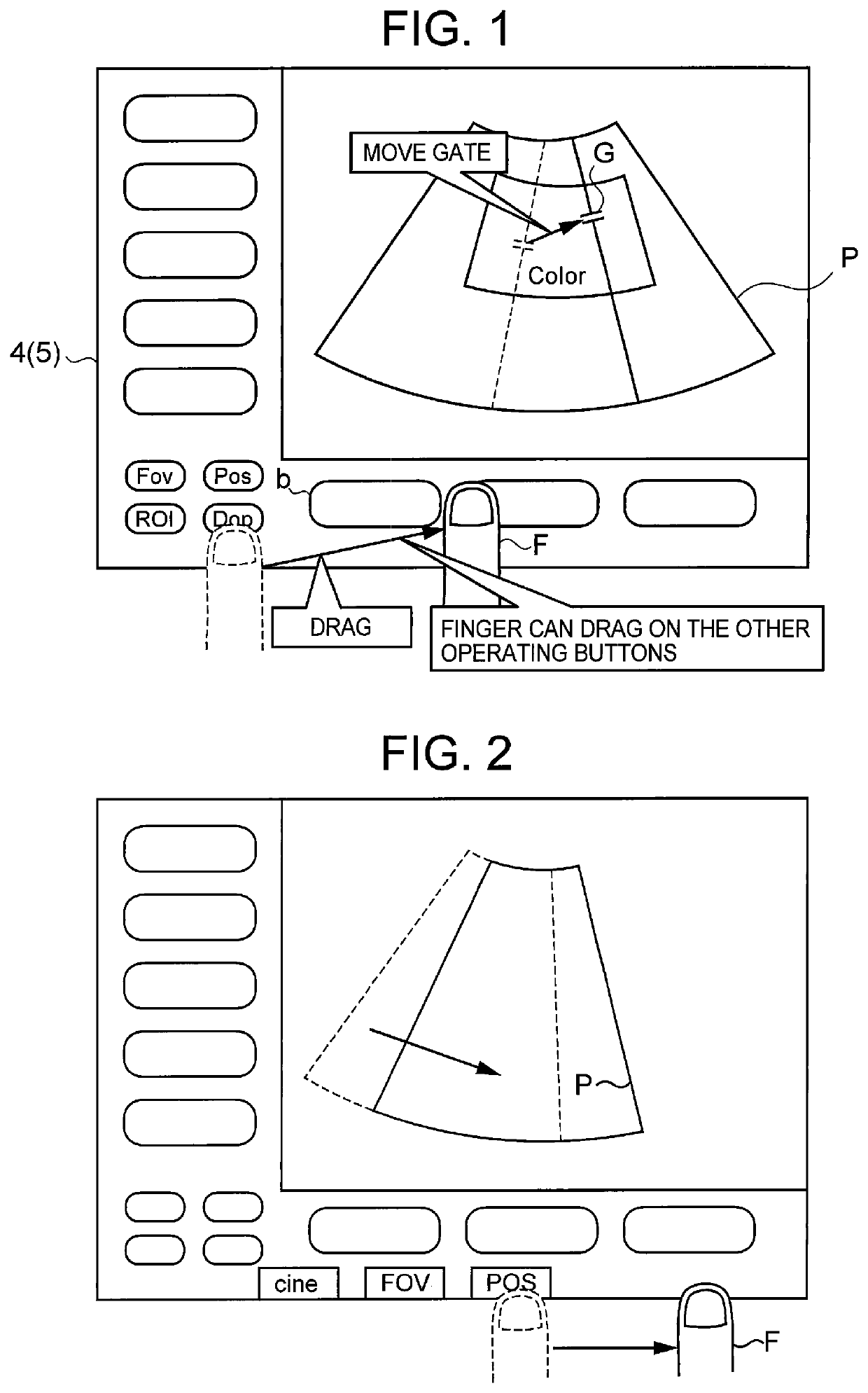
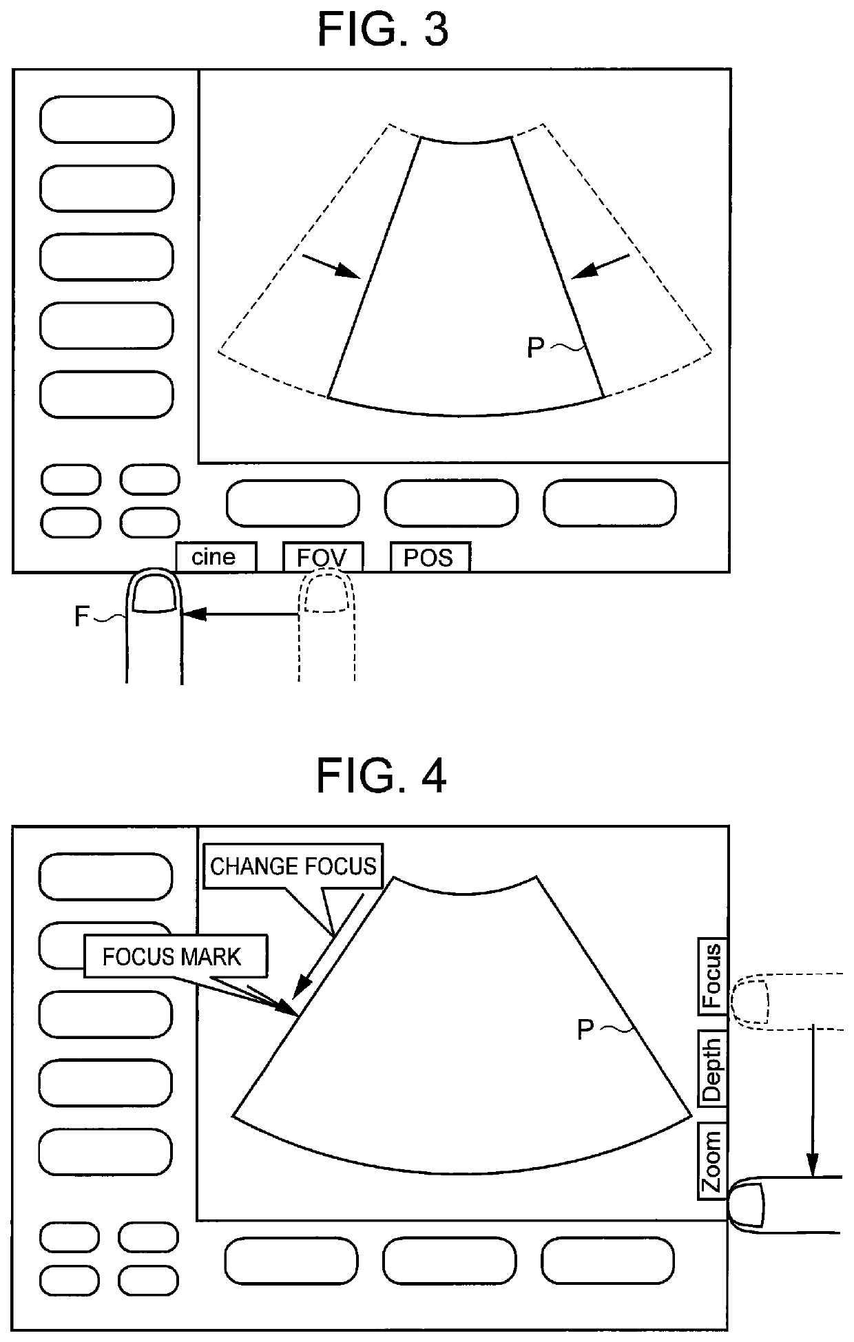
[0057]FIG. 1 is an explanatory view showing a display example of a first embodiment of an ultrasonograph according to the present invention. The display screen shown in FIG. 1 is divided into an ultrasonic image area A1 which displays an ultrasonic image P and an operating part display area A2 which displays displayed-content change buttons for selecting a change to be performed for the ultrasonic image P (for example, Fov, Pos, ROI, and Dop in the drawing) (hereinafter, also referred to as just buttons) similarly to the prior art and differs from the prior art in the following points.
[0058]First, the ultrasonic image area A1 displays only the ultrasonic image P. The ultrasonic image P does not change even if the ultrasonic image area A1 is touched for the purpose of image change according to the present invention. The ultrasonic image area A1 does not need to be provided with the touch panel but may be provided with the touch panel for another purpose. Furthermore, the operating pa...
second embodiment
[0070]FIG. 7 is an explanatory view showing a display example of a second embodiment of the ultrasonograph according to the present invention. The display screen shown in FIG. 7 is divided into an ultrasonic image area A1 which displays an ultrasonic image P and an operating part display area A2 used to specify the change to be performed for the ultrasonic image P similarly to the prior art and differs from the prior art in the following points.
[0071]First, the ultrasonic image area A1 as a first display area of the present invention displays only the ultrasonic image P. The ultrasonic image P does not change even if the ultrasonic image area A1 is touched for the image change according to the present invention. The ultrasonic image area A1 does not need to be provided with the touch panel but may be provided with the touch panel for another purpose. Furthermore, the operating part display area A2 as a second display area is provided with a touch panel. The operating part display ar...
third embodiment
[0081]FIG. 10 is an explanatory view showing a display example of a third embodiment of the ultrasonograph according to the present invention. The display screen shown in FIG. 10 is divided into an ultrasonic image area A1 which displays an ultrasonic image P and an operating part display area A2 used to perform a drag operation for the ultrasonic image P similarly to the prior art. First, the ultrasonic image area A1 as the first display area of the present invention displays only the ultrasonic image P and a cursor C. Even if the ultrasonic image area A1 is touched, the cursor C does not move. The ultrasonic image area A1 does not need to be provided with the touch panel but may be provided with the touch panel for another purpose.
[0082]Furthermore, the operating part display area A2 as a second display area is provided with a touch panel. The operating part display area A2 displays a touch pad area 1100 as a drag area used for moving the cursor C, a Start button 1101, a Set butto...
PUM
 Abstract
Description
Claims
Application Information
 - R&D
- Intellectual Property
- Life Sciences
- Materials
- Tech Scout
- Unparalleled Data Quality
- Higher Quality Content
- 60% Fewer Hallucinations
Browse by: Latest US Patents, China's latest patents, Technical Efficacy Thesaurus, Application Domain, Technology Topic, Popular Technical Reports.
© 2025 PatSnap. All rights reserved.Legal|Privacy policy|Modern Slavery Act Transparency Statement|Sitemap|About US| Contact US: help@patsnap.com


