Ultrasonograph

a technology of ultrasonograph and input speed, applied in the field of ultrasonograph, can solve the problems of difficulty in keeping a desired speed or controlling the position, and difficulty in linear input, so as to facilitate the adjustment of input speed and position, and easy to chang

Active Publication Date: 2010-12-23
KONICA MINOLTA INC
View PDF18 Cites 54 Cited by
  • Summary
  • Abstract
  • Description
  • Claims
  • Application Information

AI Technical Summary

Benefits of technology

[0025]Further, the ultrasonograph has a configuration wherein the controller allows the functions assigned to the independent function areas to be changed individually or collectively for the individual sides of the outer frame. With such a configuration, the functions assigned to the independent function area can be easily changed, and the wide variety of operations of changing parameters can be therefore performed in this area.
[0026]Furthermore, the ultrasonograph has a configuration wherein information on the function assigned to the independent function area adjacent to each side of the outer frame is displayed at the independent function area. With such a configuration, the user can easily check the function assigned to the touch panel area provided along the monitor frame.
[0027]According to the present invention, it is possible to prevent a part of a touch panel-equipped display which displays an ultrasonic tomographic image from getting dirty with fingerprints or scratches when a drag operation is used to change the displayed content of the ultrasonic tomographic image displayed on the touch panel-equipped display. Furthermore, the ultrasonic tomographic image can be made more visible.
[0028]Moreover, the present invention allows part of the touch panel area adjacent to the outer frame of the monitor to be treated as touch pads having independent functions set thereto. Sliding a finger or a tool as input means on each area along the outer frame of the monitor facilitates adjustment of the input speed and position. It is therefore possible to provide an ultrasonograph having an effect on allowing input to be performed by various institutive operation ways.

Problems solved by technology

Moreover, the conventional ultrasonograph including a touch panel as an input device has the following problems.
When intuitive input is performed by sliding a finger or the like on an entry area arranged vertically or horizontally, it is difficult to perform input in a linear fashion.
The entry area is a part of the screen and is small, where the operation is difficult to perform.
Furthermore, in the conventional ultrasonograph including the above described hard keys as the input devices, vertical or horizontal scroll using a trackball, which has high operational flexibility, has difficulties in keeping a desired speed or controlling the position.
Moreover, the trackball needs to be rolled several times for one operation and also has a problem in such an inconvenient operation.

Method used


Image

  • Ultrasonograph
  • Ultrasonograph
  • Ultrasonograph

Examples


first embodiment

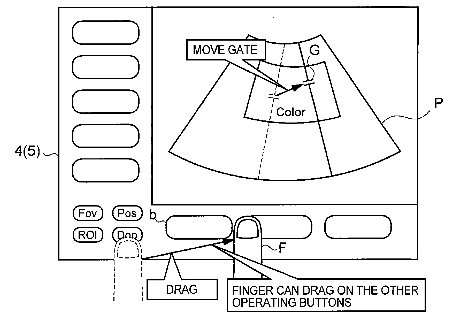
[0057]FIG. 1 is an explanatory view showing a display example of a first embodiment of an ultrasonograph according to the present invention. The display screen shown in FIG. 1 is divided into an ultrasonic image area A1 which displays an ultrasonic image P and an operating part display area A2 which displays displayed-content change buttons for selecting a change to be performed for the ultrasonic image P (for example, Fov, Pos, ROI, and Dop in the drawing) (hereinafter, also referred to as just buttons) similarly to the prior art and differs from the prior art in the following points.

[0058]First, the ultrasonic image area A1 displays only the ultrasonic image P. The ultrasonic image P does not change even if the ultrasonic image area A1 is touched for the purpose of image change according to the present invention. The ultrasonic image area A1 does not need to be provided with the touch panel but may be provided with the touch panel for another purpose. Furthermore, the operating pa...

second embodiment

[0070]FIG. 7 is an explanatory view showing a display example of a second embodiment of the ultrasonograph according to the present invention. The display screen shown in FIG. 7 is divided into an ultrasonic image area A1 which displays an ultrasonic image P and an operating part display area A2 used to specify the change to be performed for the ultrasonic image P similarly to the prior art and differs from the prior art in the following points.

[0071]First, the ultrasonic image area A1 as a first display area of the present invention displays only the ultrasonic image P. The ultrasonic image P does not change even if the ultrasonic image area A1 is touched for the image change according to the present invention. The ultrasonic image area A1 does not need to be provided with the touch panel but may be provided with the touch panel for another purpose. Furthermore, the operating part display area A2 as a second display area is provided with a touch panel. The operating part display ar...

third embodiment

[0081]FIG. 10 is an explanatory view showing a display example of a third embodiment of the ultrasonograph according to the present invention. The display screen shown in FIG. 10 is divided into an ultrasonic image area A1 which displays an ultrasonic image P and an operating part display area A2 used to perform a drag operation for the ultrasonic image P similarly to the prior art. First, the ultrasonic image area A1 as the first display area of the present invention displays only the ultrasonic image P and a cursor C. Even if the ultrasonic image area A1 is touched, the cursor C does not move. The ultrasonic image area A1 does not need to be provided with the touch panel but may be provided with the touch panel for another purpose.

[0082]Furthermore, the operating part display area A2 as a second display area is provided with a touch panel. The operating part display area A2 displays a touch pad area 1100 as a drag area used for moving the cursor C, a Start button 1101, a Set butto...


PUM


Abstract

Disclosed is a technology that prevents a part of a touch panel-equipped display displaying an ultrasonic tomographic image from getting dirty with a fingerprint or scratch when using a drag operation to change the content of the ultrasonic tomographic image displayed on the touch panel-equipped display. According to this technology, the display screen is divided into an ultrasonic image area A1 which displays an ultrasonic image P and an operating part display area A2 which displays buttons (Fov, Pos, ROI, and Dop) for selecting a change to be made in the ultrasonic image P. The operating part display area A2 has a touch panel, and when a finger F selectively touches one of the displayed buttons and is dragged, the displayed image P of the ultrasonic image area A1 is changed on the apparatus side according to the selected changes and drag direction.

Description

TECHNICAL FIELD[0001]The present invention relates to an ultrasonograph including a touch panel-equipped display.[0002]Moreover, the present invention relates to an ultrasonograph in which the content of an ultrasonic tomographic image displayed on a touch panel-equipped display can be changed using a drag operation.[0003]Furthermore, the present invention relates to an ultrasonograph in which movement of a mouse cursor displayed on a touch panel-equipped display and the content of an ultrasonic tomographic image displayed thereon can be changed using a drag operation.[0004]Still furthermore, the present invention relates to an ultrasonograph in which various types of image parameters of an ultrasonographic image displayed on a touch panel-equipped display can be changed.BACKGROUND ART[0005]One of the conventional techniques of an ultrasonograph including a touch panel-equipped display is described in Patent Document 1 below. FIG. 24 shows a conventional display example in which a d...

Claims


Application Information

Patent Timeline
Patent Type & Authority Applications(United States)
IPC IPC(8): G06F3/041
CPCA61B8/00A61B8/467A61B8/465G06F3/04883A61B8/469A61B8/463G06F3/048
Inventor FUKAI, SEIICHISAITO, MASAHIROSAKAI, TAKASHIOKAMOTO, YUKIKO
Owner KONICA MINOLTA INC
Why Eureka
Try Eureka