
Mounting device and carton flow bed

a technology of mounting device and flow bed, which is applied in the direction of racks, rod connections, applications, etc., can solve the problems of increasing weight and friction without significantly improving the stability of the plug connection, and achieve the effect of simplifying the construction of the rack

Active Publication Date: 2020-09-08
INTERROLL HLDG
View PDF37 Cites 1 Cited by
  • Summary
  • Abstract
  • Description
  • Claims
  • Application Information

AI Technical Summary

Benefits of technology

The patent text describes a mounting device for connecting two support beams of a carton flow bed rack. The mounting device is durable, strong, and stable, and can be easily and quickly installed. The mounting device allows for the arrangement of further elements of the rack while keeping the plug in a secure position. This simplifies the construction of the rack and allows for a fast and efficient installation process. The technical effects of this patent text are improved durability, strength, and stability of the mounting device, as well as a more simplified and efficient installation process for the rack.

Problems solved by technology

The problem relates to providing an improved connection for two support beams of a rack, in particular of a carton flow bed rack that requires increased stability.
Further arms or sections of the plug may be omitted that would increase the weight and the friction without significantly improving the stability of the plug connection.

Method used


Image

  • Mounting device and carton flow bed
  • Mounting device and carton flow bed
  • Mounting device and carton flow bed

Examples


first embodiment

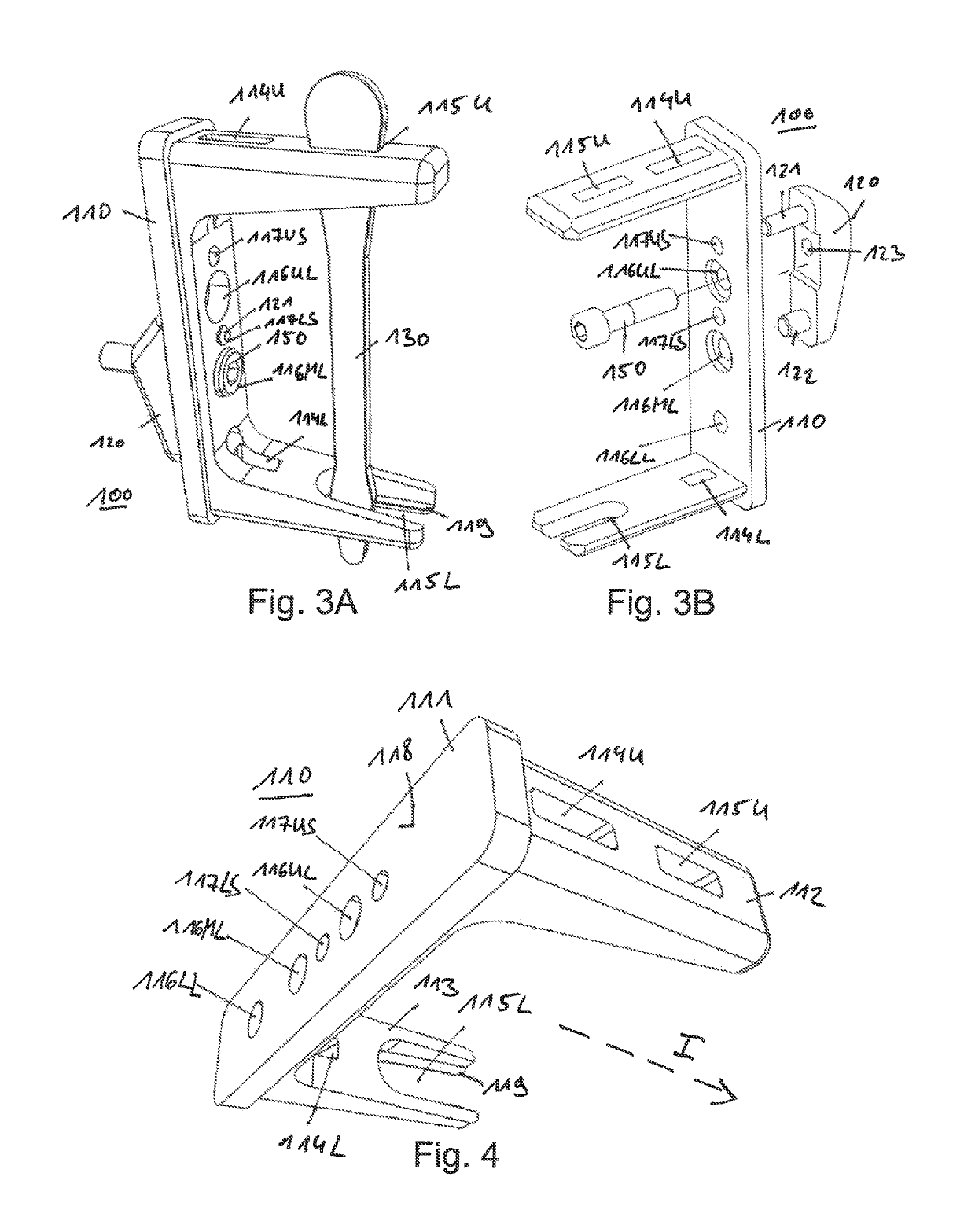
[0080]FIG. 3A shows a perspective view of the mounting device 100. The mounting device comprises a plurality of separate elements.

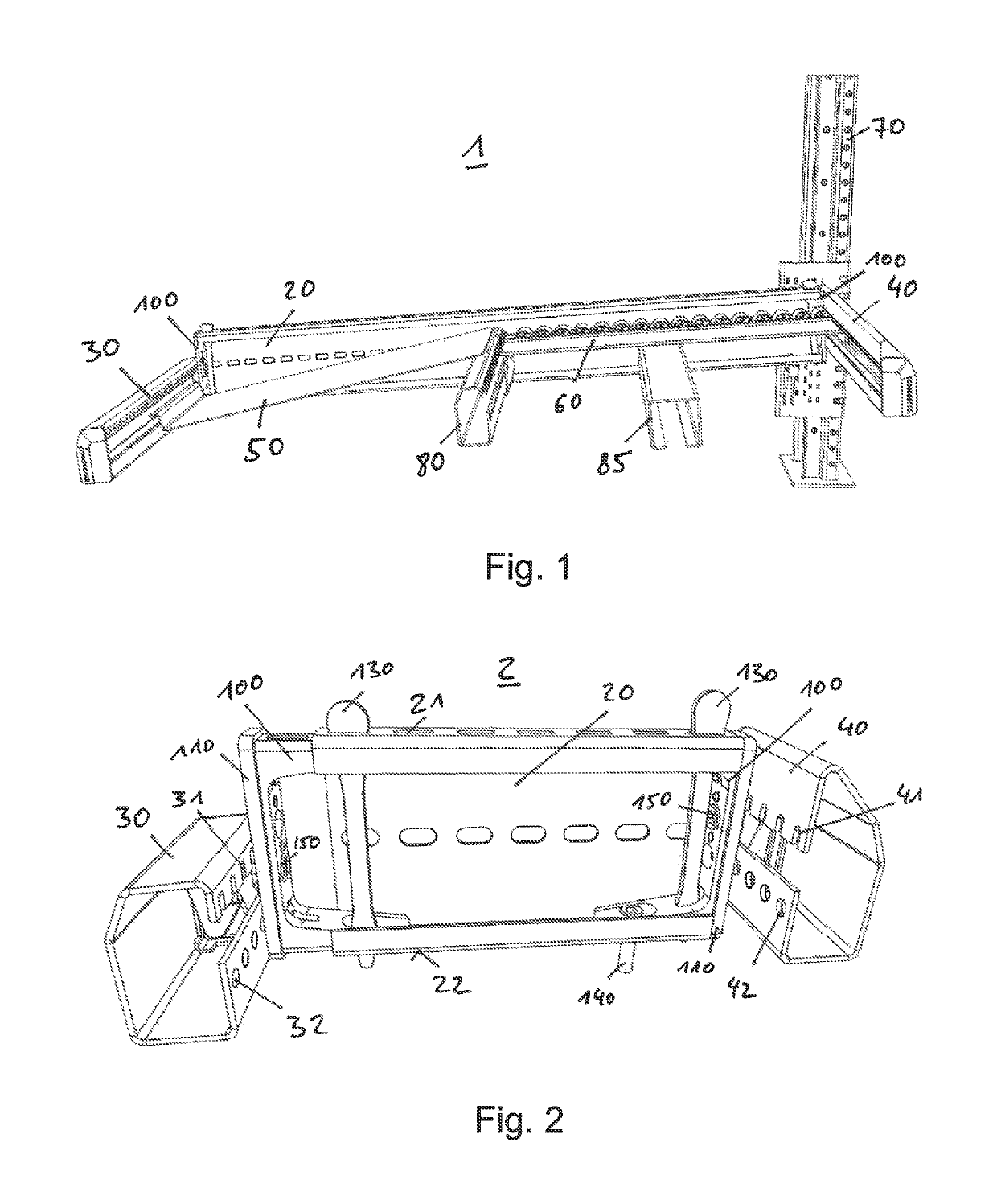
[0081]In the shown embodiment, the mounting device 100 comprises a plug 110, an engaging element 120, and a key 130. The mounting device 100 may comprise further elements, for example a nut screw 150 and / or a plug screw 140 (as shown in FIG. 2). The engaging element 120 is fixed to the plug 110 by pins and / or the nut screw 150. The engaging element 120 may be fixed to the plug 110 at different height positions and / or engaging-positions. The engaging element 120 enables fixation of the end beam 30 and / or 40 (see FIG. 2) with respect to the plug 110 of the mounting device 100.

[0082]The key 130 enables fixation of the plug 110 within the side beam 20 in different plug positions of the plug 110.

second embodiment

[0083]FIG. 3B shows a perspective view of the mounting device 100, wherein the key 130 is omitted. The mounting device 100 is shown in a state wherein the engaging element 120 is not yet fixed to the plug 110.

[0084]The mounting devices shown in FIGS. 3A and 3B may have similar components and / or elements, which is why their features are referred to with the same reference signs.

[0085]The elements of the mounting device 100 are further described in reference to the following figures.

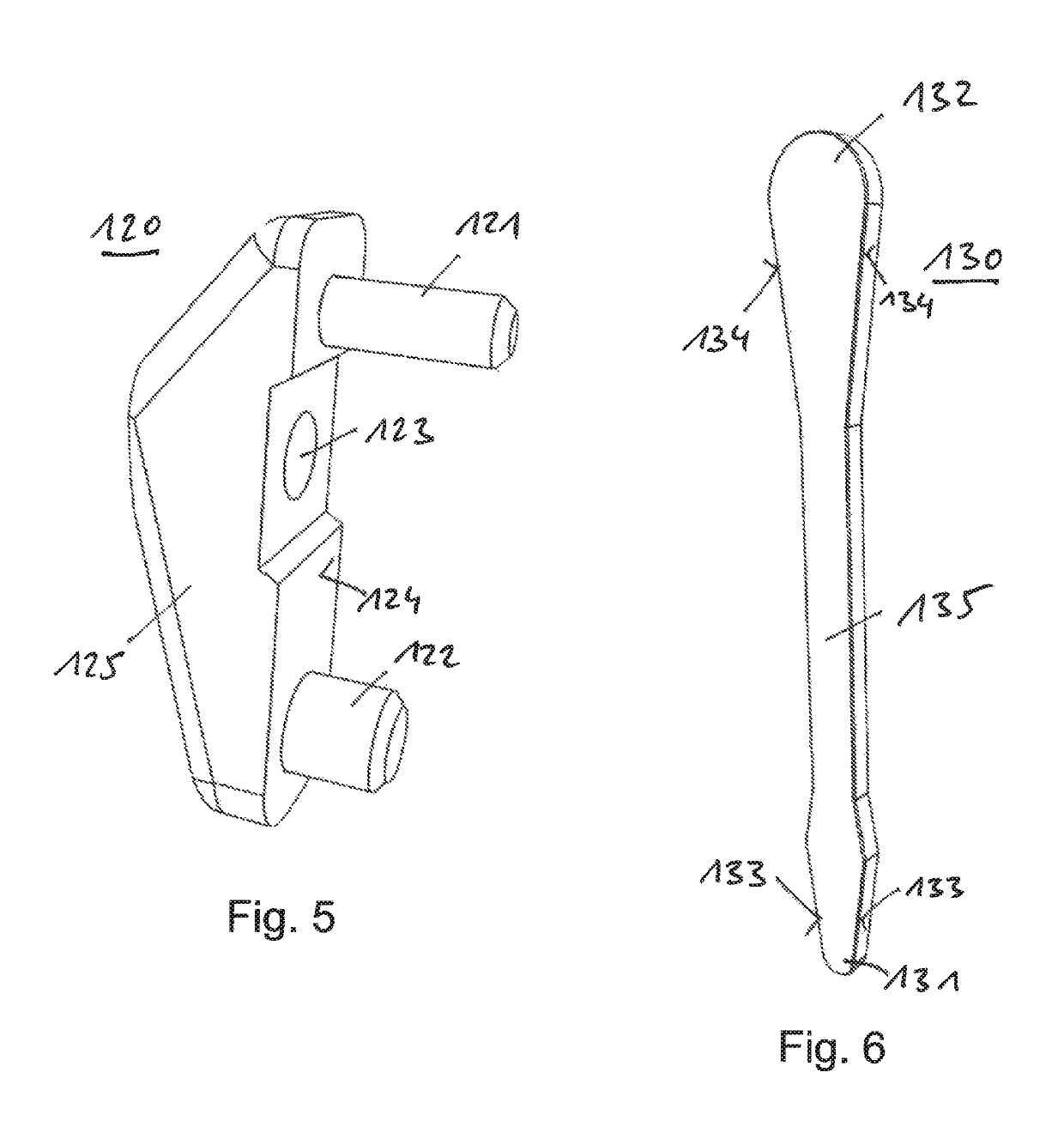
[0086]FIG. 4 shows a perspective view of the plug 110 of the mounting device 100. The plug 110 comprises a base 111 which may be implemented as the base of a clevis and / or bracket. The base 111 may be shaped as a substantially rectangular plate. The shape of this plate and / or the base 111 may substantially correspond to the cross-section of the side beam 20. In particular, a shape of the base 111 may be implemented slightly larger than the cross-section of the side beam 20. Thus, the base 111 may serve as ...


PUM


Abstract

A mounting device (100) is provided for connecting two substantially horizontally aligned support beams (20, 30, 40) of a carton flow bed rack (1; 2). The mounting device (100) has a plug (110) pluggable into an end of a first support beam (20) of the support beams. A key (130) is provided as a wedge for fixing the plug (110) in the first support beam (20). An engaging element (120) is arranged at the plug (110). The engaging element (120) is provided to engage a second support beam (30; 40) of the two support beams. The plug (110) is fixable to the first support beam (20) in at least two different plug-positions by means of the key (130).

Description

BACKGROUNDField of the Invention[0001]The invention relates to a mounting device and method for connecting two support beams of a rack, in particular of a carton flow bed rack.Description of the Related Art[0002]Carton flow bed racks are used to store and / or distribute loads, in particular parcels, cartons, and / or other goods. Carton flow bed racks are characterized in that they comprise a load side from which the rack is loaded and an unload side from which the rack is unloaded. There are carton flow bed racks that are loaded and unloaded at the same side, and others that are loaded and unloaded at different, e.g. opposite, sides. Carton flow bed racks may comprise wheel tracks to transport loads from one side of the rack to the other side.[0003]For enabling a stable support, e.g. of these wheel tracks and the loads, support beams are provided. In particular at edges of the rack, two support beams are connected to each other substantially perpendicular to each other. This connectio...

Claims


Application Information

Patent Timeline
Patent Type & Authority Patents(United States)
IPC IPC(8): A47B96/06B65G1/08A47F5/10A47F1/12B65G1/02F16B7/04
CPCA47B96/06A47F1/12B65G1/08A47F5/10B65G1/023B65G1/02F16B7/0446B65G35/00F16B7/00
Inventor LAPLACE, JEAN MICHELMERIEAU, HERVE
Owner INTERROLL HLDG
Learn More