Resin fuel tank and blow molding mold for molding the same

a fuel tank and resin technology, applied in the direction of transportation and packaging, propulsion parts, other domestic articles, etc., can solve the problems of excessive thickness of the distal end portion of the pair of excessively thick portions will be formed at the inner side of the fuel tank, and the cross-sectional shape of the notch will become sharp, so as to achieve the effect of suppressing the enlargement of the notch that forms at the inner sid

Active Publication Date: 2020-10-13
TOYOTA JIDOSHA KK
View PDF11 Cites 0 Cited by
  • Summary
  • Abstract
  • Description
  • Claims
  • Application Information

AI Technical Summary

Benefits of technology

[0006]In consideration of the above circumstances, an object of preferred embodiments is to provide a resin fuel tank and a blow molding mold for molding a resin fuel tank that can decrease or prevent the generation of a large stress at the time when load is inputted from the exterior.

Problems solved by technology

As a result, in the state in which the fuel tank is molded, a pair of excessively-thick portions is formed at the inner side of the fuel tank.
If the excessively-thick portions are large, there is the tendency for the distal end portion of the cross-sectional shape of the notch to become sharp toward the outer side of the fuel tank.
Due thereto, a pair of excessively-thick portions will be formed at the inner side of the fuel tank main body portion of the fuel tank that is the molded product.
Further, a notch is formed between these excessively-thick portions, and, if the excessively-thick portions are large, the distal end portion of the cross-sectional shape of the notch tends to become sharp toward the outer side of the fuel tank.
By the way, when the parison is nipped by the first molding mold and the second molding mold, portions of the parison are pushed-into the first cavity portion and the second cavity portion side by the molds, and it is thought that a pair of excessively-thick portions will form at the inner side of the molded product.
Further, a notch forms between these excessively-thick portions, and, if the excessively-thick portions are large, the distal end portion of the cross-sectional shape of the notch tends to become sharp toward the outer side of the molded product.

Method used


Image

  • Resin fuel tank and blow molding mold for molding the same
  • Resin fuel tank and blow molding mold for molding the same
  • Resin fuel tank and blow molding mold for molding the same

Examples


Embodiment Construction

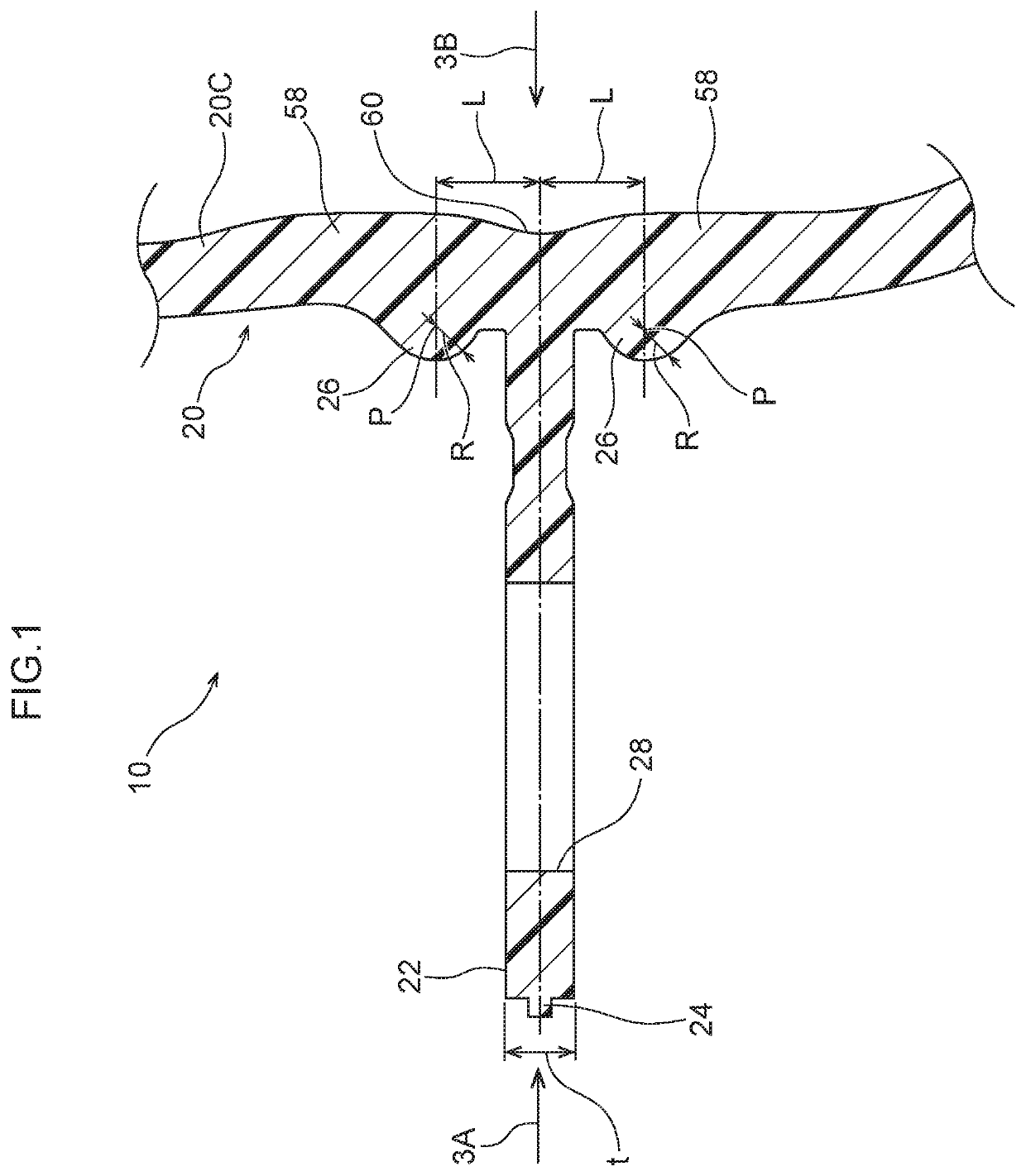
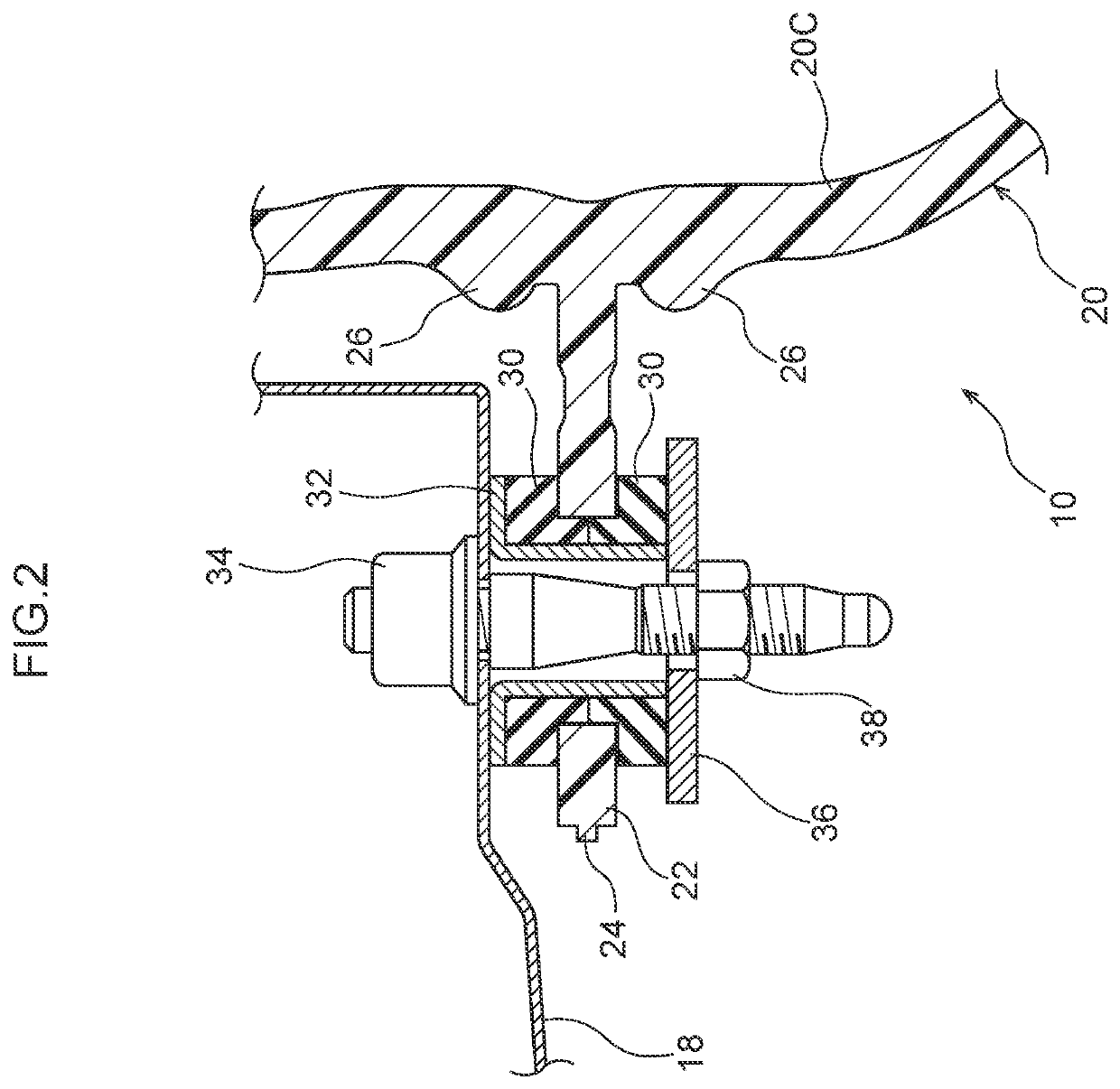
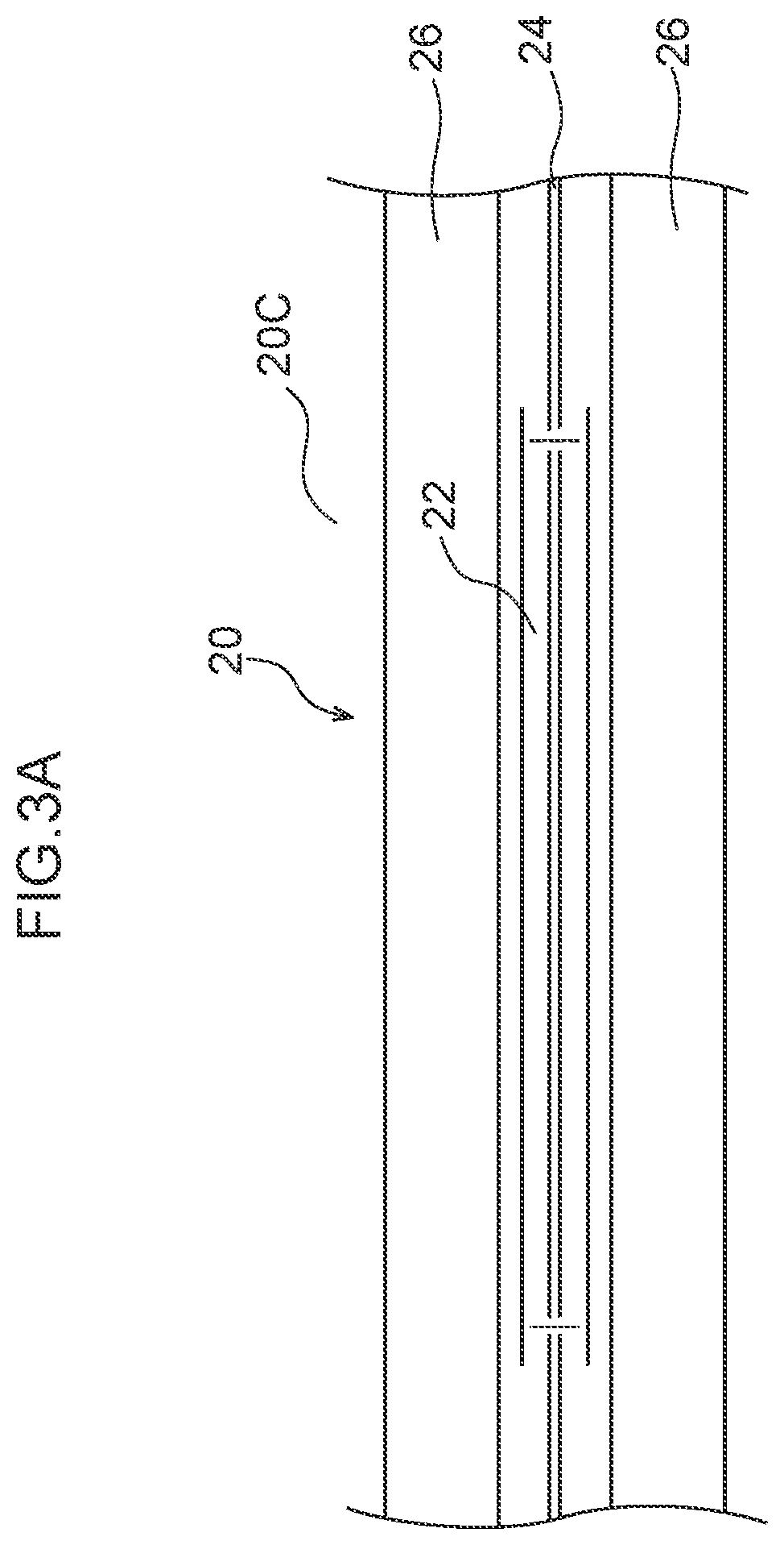
[0037]An example of an embodiment of a resin fuel tank relating to the present invention is described hereinafter by using FIG. 1 through FIG. 6, and then a blow molding mold for molding the resin fuel tank is described by using FIG. 7. Note that arrow FR that is shown appropriately in the respective drawings that are used in describing the resin fuel tank indicates the vehicle front side, arrow UP indicates the vehicle upper side, and arrow RH indicates the vehicle transverse direction right side.

[0038]First, by using FIG. 5 and FIG. 6, description is given of the structure of a vehicle body 14 of a vehicle 12 in which a fuel tank 10, which serves as a resin fuel tank relating to the present embodiment, is installed. The vehicle body 14 has a floor panel 16 that is formed by press-molding a steel plate, and that structures a part of a floor portion that is at the vehicle lower side of the vehicle body 14, and that extends in the vehicle longitudinal direction and the vehicle transv...


PUM

PropertyMeasurementUnit
moldingaaaaaaaaaa
internal pressureaaaaaaaaaa
timeaaaaaaaaaa

Abstract

A resin fuel tank includes a peripheral wall portion that is configured to structure a portion of a fuel tank main body portion that is made of resin and in which fuel is stored, the peripheral wall portion having a parting line portion that is visible from an outer side of the fuel tank main body portion, and a projecting portion that is solid, is disposed along the parting line portion, and is configured to project outward, integrally with the peripheral wall portion, from the peripheral wall portion toward the outer side of the fuel tank main body portion.

Description

CROSS-REFERENCE TO RELATED APPLICATION[0001]This application claims priority under 35 USC 119 from Japanese Patent Application No. 2017-5467 filed Jan. 16, 2017, the disclosure of which is incorporated by reference herein in its entirety.BACKGROUNDTechnical Field[0002]Preferred embodiments relate to a resin fuel tank and a blow molding mold for molding the same.Related Art[0003]Japanese Patent Application Laid-Open (JP-A) No. 2014-148227 discloses an invention relating to a vehicle body mounting structure for a fuel tank. In this vehicle body mounting structure for a fuel tank, a bottom wall portion of the fuel tank is joined by joining means to a band lower member that is fixed to a vehicle body and that holds the fuel tank. A top wall portion of the fuel tank is joined by joining means to a vehicle body structural part. Therefore, deformation of the fuel tank due to changes in internal pressure can be suppressed.[0004]However, in the aforementioned related art, because the fuel ta...

Claims


Application Information

Patent Timeline
Patent Type & Authority Patents(United States)
IPC IPC(8): B60K15/03B60K15/067B60K15/06B29C49/04B60K15/063B29C49/48B29C43/00B29C49/20B29L31/00
CPCB60K15/03177B60K15/067B60K2015/03118B29C43/00B29C2793/0054B29C49/482B29C49/04B60K2015/0636B29L2031/7172B29C2049/4805B29C2049/2069B60K2015/0638B60K2015/03032B29C49/48B60K15/063B60K2015/0634
Inventor MIKI, MASAHARU
Owner TOYOTA JIDOSHA KK
Why Eureka
Try Eureka