Position detecting sensor and position detector

a technology of position detection and sensor, applied in the field of position detection sensors, can solve problems such as difficulty in obtaining uniform light permeability over the entire sensor area

Active Publication Date: 2014-11-11
WACOM CO LTD
View PDF8 Cites 4 Cited by
  • Summary
  • Abstract
  • Description
  • Claims
  • Application Information

AI Technical Summary

Benefits of technology

[0035]According to the position detecting sensor of the present invention, the dummy patterns are disposed in the sensor pattern having a grid structure, whereby uniform light permeability can be ensured over the entire sensor area. In addition, when the position detecting sensor is superposed on the display surface of a display device, it is possible to either decrease or prevent generation of the Moire fringes, due to the disposition of the dummy patterns, between the pixel disposition in the display surface and the position detecting sensor. Moreover, a position indicated by the indication body can be precisely detected without any correction processing in the signal processing circuit.

Problems solved by technology

For this reason, since the area in which no light-permeable electrode is formed is different in light permeability from a portion in which the light-permeable conductive pattern is formed, it becomes difficult to obtain uniform light permeability over the entire sensor area (for the purpose of ease in viewing the display surface).

Method used


Image

  • Position detecting sensor and position detector
  • Position detecting sensor and position detector
  • Position detecting sensor and position detector

Examples


first embodiment

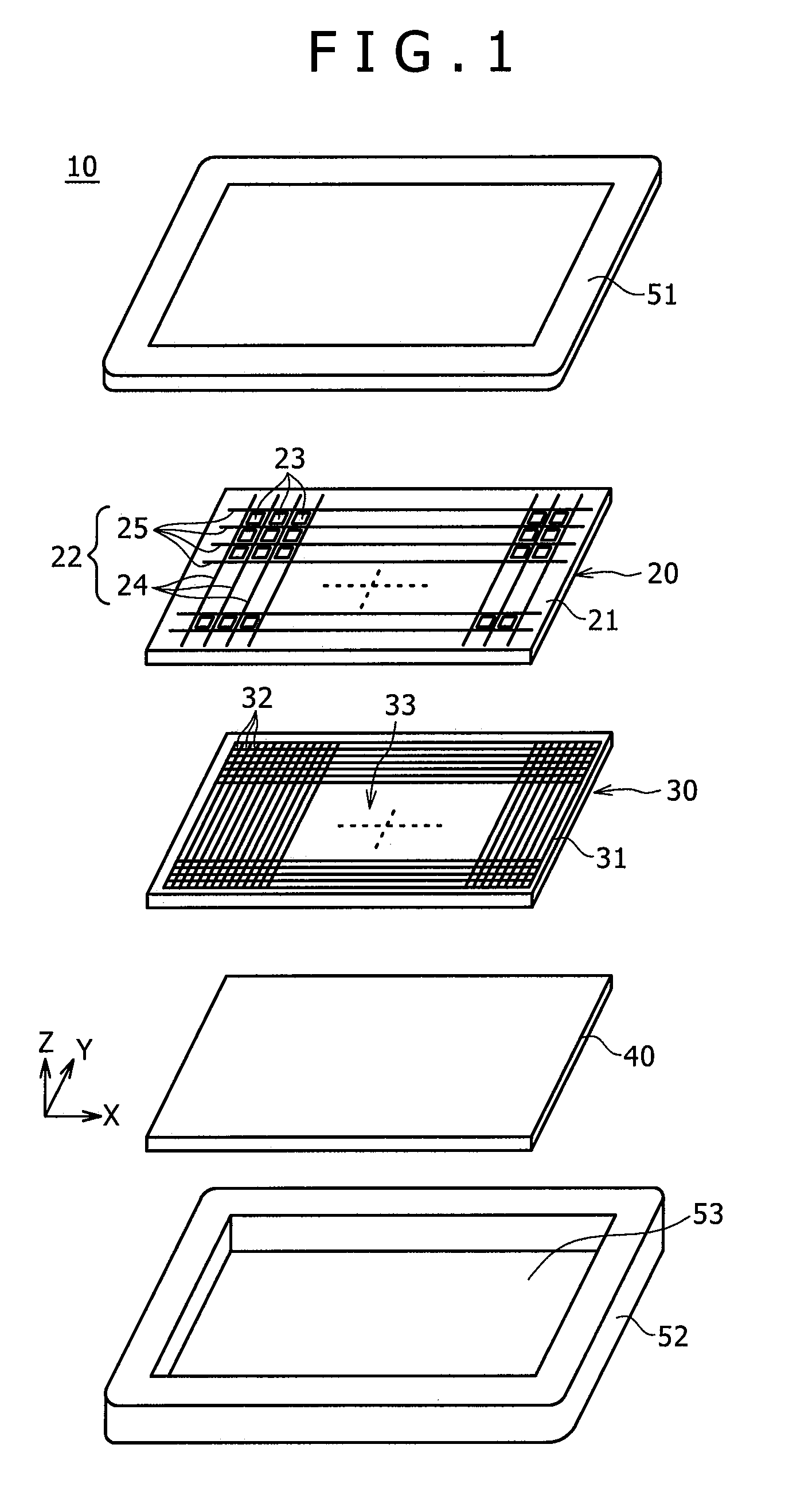
[0047]FIG. 1 is an exploded perspective view showing an example of a position detector including a first embodiment of a position detecting sensor according to the present invention. The example shown in FIG. 1 illustrates a construction of a tablet device, including a position detecting sensor for detecting a position on a display surface of a display device indicated by, for example, a pen (stylus).

[0048]The tablet device 10 of the example, as shown in FIG. 1, is composed of the position detecting sensor 20, a Liquid Crystal Display (LCD) device 30 as an example of the display device, a printed wiring board 40, and an upper case 51 and a lower case 52 that form a chassis of the tablet device 10.

[0049]As shown in FIG. 1, the LCD 30 includes a display surface 33, on which a large number of display pixels 32 are disposed in the X-axis direction (in a transverse or horizontal direction) on an LCD substrate 31, and a large number of display pixels 32 are also disposed in the Y-axis dir...

second embodiment

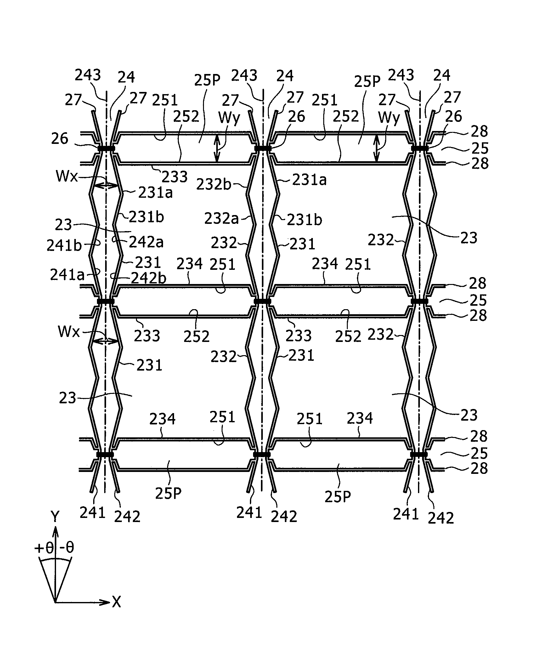
[0101]When the dummy pattern 23 composed of an ITO film having the same light transmittance as that of each of the first transparent electrodes 24 and the second transparent electrodes 25 is formed in the area, which is surrounded by two adjacent first transparent electrodes 24 and two adjacent second transparent electrodes 25 in the position detecting sensor 20 utilizing the capacitive system, as in the first embodiment described above, a distance “d” between the first transparent electrode 24 and the second transparent electrode 25 is shortened due to the presence of the dummy pattern 23 composed of the conductive member. For this reason, a coupling capacitance C (=k·S / d (k is a proportional constant, and S is a facing area of electrodes)) between the first transparent electrode 24 and the corresponding second transparent electrode 25 becomes large.

[0102]In the cross-point capacitive system, a capacitance change that occurs when the indication body, such as a finger or a position ...

modification examples

of the Second Embodiment

[0120]The second embodiment has been described in such a way that the contours with respect to the Y-axis direction of the plural small dummy patterns 61, 62, 63, and 64 have the inclinations of ±θ in the divided dummy patterns DP. However, it is not necessary, for example, for the two small dummy patterns 61 and 62 disposed in the X-axis direction to have the same parallelogram. As described above, it is only necessary for the divided dummy pattern DP to have a shape corresponding to the shapes of the first transparent electrodes 24 and the second transparent electrodes 25, respectively, so that uniform transmittance can be ensured for the entire position detecting sensor 60. In addition, it is also only necessary to set the inclination angles of the contours of the small dummy patterns 61, 62, 63, and 64 to the determined values, respectively, with respect to the disposition direction of the pixels 32 of the LCD 30 so as to decrease or prevent the generatio...


PUM


Abstract

A position detecting sensor includes a grid structure composed of plural electrodes extending in a first direction and plural electrodes extending in a second direction perpendicular to the first direction. The electrodes have light permeability. In a rectangular area defined by four cross-points, where two adjacent electrodes extending in the first direction and two adjacent electrodes extending in the second direction cross each other, a dummy pattern is disposed so as to provide uniform optical characteristics for the sensor. At least some of the electrodes extending in the first direction are shaped to include inclinations relative to the first direction, so as to minimize the Moire effect that may develop between the electrodes and an array of pixels in an overlaid display device. Also, at least some of the electrodes extending in the first direction are shaped to be line-symmetric about a straight line extending in the first direction.

Description

CROSS-REFERENCE TO RELATED APPLICATION[0001]The present application claims priority under 35 U.S.C. 119(a) of Japanese Application No. 2011-155285, filed Jul. 14, 2011, the entire content of which is incorporated herein by reference.BACKGROUND[0002]1. Technical Field[0003]The present invention relates to a position detecting sensor, which is disposed so as to be superposed on a display surface of a display device such as a Liquid Crystal Display (LCD) device or the like, in order to detect a position where an input manipulation is carried out by an indication body, and a position detector that incorporates such position detecting sensor.[0004]2. Description of the Related Art[0005]A position detector for detecting a position indicated by an indication body, such as a finger or a pen, is well known. Various types of position detecting systems may be used in the position detector, such as a resistance film system, an electromagnetic induction system, and a capacitive system. The capac...

Claims


Application Information

Patent Timeline
Patent Type & Authority Patents(United States)
IPC IPC(8): G06F3/044G06F3/046G01B11/14
CPCG06F3/046G06F3/044G06F3/0446G06F3/0412G06F3/03545G06F3/041G06F2203/04106
Inventor IWAMOTO, NAOHISA
Owner WACOM CO LTD
Why Eureka
Try Eureka