Light emitting device and vehicle

A technology for lighting devices and vehicles, which is applied to road vehicles, signal devices, lighting devices, etc., can solve the problems of inability to enhance the three-dimensional sense of light, poor uniformity of light, and limited space for light-emitting elements, so as to enhance the three-dimensional sense and diversify , Light energy conduction and distribution uniform, the effect of uniform distribution of luminous energy

Pending Publication Date: 2020-10-13
HASCO VISION TECHNOLOGY CO LTD
View PDF0 Cites 1 Cited by
  • Summary
  • Abstract
  • Description
  • Claims
  • Application Information

AI Technical Summary

Problems solved by technology

[0004] Based on this, it is necessary to provide a light-emitting device and a vehicle for the problem of limited space for arranging light-emitting elements in the traditional side-lighting scheme, and the problem that the uniformity of light-emitting is not good, and the three-dimensional effect of light-emitting cannot be enhanced.

Method used


Image

  • Light emitting device and vehicle
  • Light emitting device and vehicle
  • Light emitting device and vehicle

Examples


Embodiment Construction

[0037] The present invention will be further described below in conjunction with accompanying drawing.

[0038] In order to facilitate the understanding of the present invention, various embodiments of the present invention defined by the claims will be described more fully below with reference to the relevant drawings. Preferred embodiments of the invention have been shown in the drawings, which contain various specific details to facilitate that understanding but which should be regarded as exemplary only. However, the present invention can be embodied in many different forms and is not limited to the embodiments described herein. Accordingly, those of ordinary skill in the art will recognize that changes and modifications of the various embodiments described herein can be made without departing from the scope of the invention as defined in the appended claims. Also, descriptions of well-known functions and constructions may be omitted for clarity and conciseness.

[0039]...


PUM

PropertyMeasurementUnit
transmittivityaaaaaaaaaa

Abstract

The present invention relates to a light emitting device comprising: a shell, a light-emitting component which is arranged in the shell and used for emitting light, a light guide part which is arranged in the shell and close to the side edge of the shell, wherein the end of the light guide part faces the light-emitting component and is used for allowing light emitted by the light-emitting component to enter, and then the light is guided out in the light guide direction, and a light uniformizing part which is installed on the side edge of the shell in a penetrating mode and comprises a light inlet part arranged inside the shell and a light outlet part arranged outside the shell, wherein the light inlet part is located in the light guide direction of the light guide part so that light guidedout by the light guide part can enter the light uniformizing part, and the light outlet part is used for evenly diffusing the light entering the light uniformizing part and uniformized by the light uniformizing part outwards. According to the embodiment, the occupied space in the automobile lamp is very small, and layout and design of a light-emitting form can be conducted in a narrow space, theside surface of the car lamp can emit light uniformly, and the product has a three-dimensional uniform light-emitting effect in the side surface area.

Description

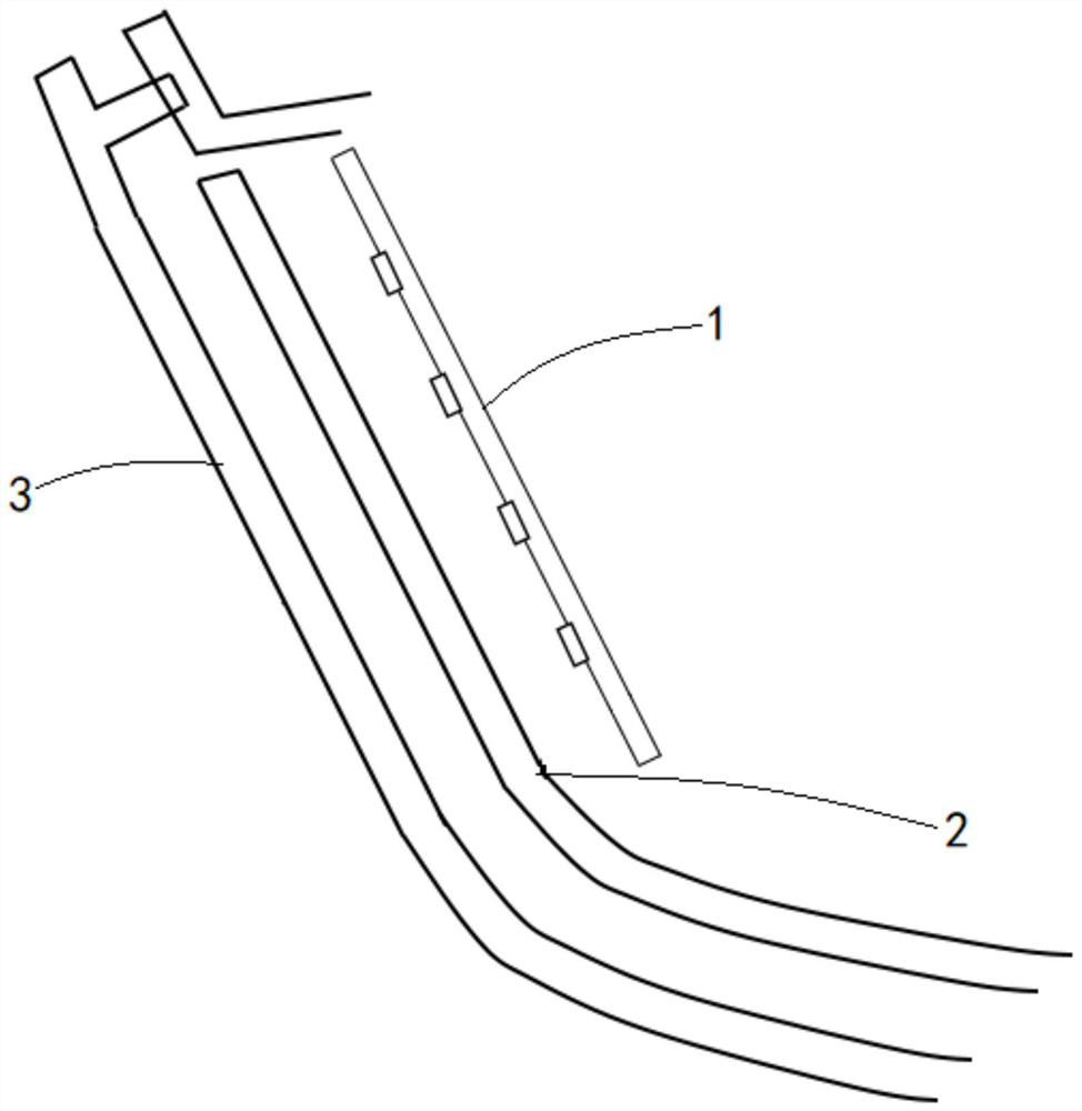
technical field [0001] The invention relates to the field of structural design, in particular to a light emitting device and a vehicle. Background technique [0002] At present, in order to meet the needs of styling and the special needs of lighting methods, more and more automotive lamps and lanterns use more artistic design methods, and the shapes become more diversified. How to realize artistic modeling in traditional automotive lamps, meet the styling needs of automotive lamps as much as possible, and meet customer requirements have become a new trend in styling. [0003] In order to make the light more three-dimensional, many car manufacturers will design to enhance the light effect of the side area. In the traditional implementation, the LED is directly used to make the side area emit light, for example figure 1 As shown in the side lighting scheme, the LED circuit board assembly 1 is fixed in the side area of ​​the car light, the surface of the car light is the ligh...

Claims


Application Information

Patent Timeline
Patent Type & Authority Applications(China)
IPC IPC(8): F21S41/141F21S41/20F21S41/24F21S43/14F21S43/20F21S43/236F21W107/10F21Y115/10
CPCF21Y2115/10F21S41/141F21S41/20F21S41/24F21S43/14F21S43/20F21S43/236F21W2107/10
Inventor 卢梦奇鲍阿彤游学兵张腾顾丹赵磊金龚明
Owner HASCO VISION TECHNOLOGY CO LTD
Why Eureka
Try Eureka