Lens cover and LED lighting device having lenses arranged at positions corresponding to LED light sources

a technology of led light source and lens cover, which is applied in the direction of lighting and heating equipment, instruments, and ways, etc., can solve the problems of high maintenance cost, high consumption of electricity, and short usage li

Active Publication Date: 2020-11-10
AMOSENSE
View PDF13 Cites 0 Cited by
  • Summary
  • Abstract
  • Description
  • Claims
  • Application Information

AI Technical Summary

Benefits of technology

[0011]According to an embodiment of the present disclosure, it is possible to provide the lighting device, which satisfies the recommendations of the Road Traffic Act, such as an average brightness, a uniformity ratio of illumination, and a unified glare rating even if the lighting device of a relatively low height is installed on the roadside.

Problems solved by technology

However, these lamps consume a lot of electricity, have a short usage life, have a high maintenance cost, and have an environmental pollution problem.
However, there is a problem in that the circular light distribution lens has a large brightness difference between the center and the periphery of the light distribution area.
As described above, if only any one of the oval lens and the circular lens is used as the light distribution lens in the LED lighting device, the light distribution areas of adjacent lighting devices may overlap each other to increase the brightness, but dark portions (I, II) may be formed or distribution of lighting intensity may also be uneven.
The formation of such a dark portion or non-uniformity of the lighting intensity may cause the driver to be optical illusion and fatigue, which may act as a serious factor that may cause a traffic accident.
Further, a road lighting device such as a general street lamp is installed at a height of about 12 m or more, there is a hassle to necessarily use a separate maintenance vehicle at the time of maintenance work of the lighting device.

Method used


Image

  • Lens cover and LED lighting device having lenses arranged at positions corresponding to LED light sources
  • Lens cover and LED lighting device having lenses arranged at positions corresponding to LED light sources
  • Lens cover and LED lighting device having lenses arranged at positions corresponding to LED light sources

Examples


Embodiment Construction

[0022]Hereinafter, the present disclosure will be described with reference to the accompanying drawings. However, the present disclosure may be implemented in various forms, and accordingly, is not limited to the embodiment described herein. Further, a portion irrelevant to the description has been omitted in the drawings for clearly describing the present disclosure, and like portions has been denoted by like reference numerals throughout the specification.

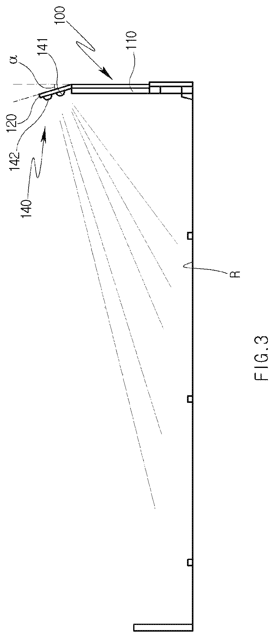
[0023]Referring to FIG. 3, an LED street lamp 100 according to an embodiment of the present disclosure includes a post 110, a head 120, and a cover 140.

[0024]The post 110 is fixedly installed on the installation surface (ground) of the roadside along the longitudinal direction of the road, and has a predetermined height. In an embodiment, the post 110 may be formed at a low height of 3 m or less. For example, if an LED lighting device according to an embodiment is installed adjacent to a bridge, the length of the post 110 may be ...


PUM

PropertyMeasurementUnit
angleaaaaaaaaaa
angleaaaaaaaaaa
heightaaaaaaaaaa

Abstract

The present disclosure proposes a lens cover and an LED lighting device including the same, which may minimize occurrence of a dark portion even while expanding a light distribution area of an LED light source. The proposed lens cover includes a plurality of first light distribution lenses and a second light distribution lenses having different shapes from each other, and the first light distribution lens and the second light distribution lens are mixedly arranged at positions corresponding to the plurality of LED light sources.

Description

TECHNICAL FIELD[0001]The present disclosure relates to an LED lighting device mounted with a plurality of LED light sources.BACKGROUND ART[0002]In general, various types of lighting devices may be installed in a road or a tunnel. As a conventional lighting device, a sodium lamp, a halogen lamp, a mercury lamp or a metal halide lamp have been used. However, these lamps consume a lot of electricity, have a short usage life, have a high maintenance cost, and have an environmental pollution problem.[0003]Accordingly, efforts to apply a light emitting diode (LED) light source have been continued to solve the problem of power consumption according to the use of the lamp described above and to extend the lamp replacement cycle according to the extension of the lamp life.[0004]The lighting device using the LED as a light source disposes a light distribution lens at a position corresponding to a light source unit, and uses by diffusing or collecting the light of the LED light source as neces...

Claims


Application Information

Patent Timeline
Patent Type & Authority Patents(United States)
IPC IPC(8): F21V5/04F21S8/08F21W111/02
CPCF21S8/088F21V5/045F21W2111/02F21V5/007F21S8/08F21V5/04G02B3/00F21S8/085F21W2131/103
Inventor SHIN, GYU WEON
Owner AMOSENSE
Why Eureka
Try Eureka