Check patentability & draft patents in minutes with Patsnap Eureka AI!

Plug-and-play electronic capacitor for voltage regulator modules applications

a voltage regulator module and electronic capacitor technology, applied in the direction of electric variable regulation, process and machine control, instruments, etc., can solve the problems of increased complexity, large pcb area, and weak regulation during unloading transien

Active Publication Date: 2020-11-17
B G NEGEV TECH & APPL LTD
View PDF46 Cites 0 Cited by
  • Summary
  • Abstract
  • Description
  • Claims
  • Application Information

AI Technical Summary

Benefits of technology

The TSU effectively reduces output capacitance requirements, enhances transient response, and maintains steady-state voltage precision, allowing for increased power density and reduced volume without adding complexity or modifying the existing VRM design.

Problems solved by technology

On the other hand, sizing of the output capacitor in VRM applications primarily depends on the load transient magnitude and rate, and therefore consumes a significant portion of PCB area.
The main limitation of these methods is the weak regulation during unloading transient due to the high input-to-output conversion ratio.
The additional layers of complexity are the prominent reason for the lack of absorbance, of such promising technology, in commercial VRM applications.

Method used


Image

  • Plug-and-play electronic capacitor for voltage regulator modules applications
  • Plug-and-play electronic capacitor for voltage regulator modules applications
  • Plug-and-play electronic capacitor for voltage regulator modules applications

Examples


Embodiment Construction

[0066]The present invention provides a plug-and-play Transient Suppression Unit (TSU) for voltage regulator module (VRM) applications. The TSU trades the output capacitance by a silicon-based solution without affecting the steady-state operation, the originally designed compensation network and the input filter.

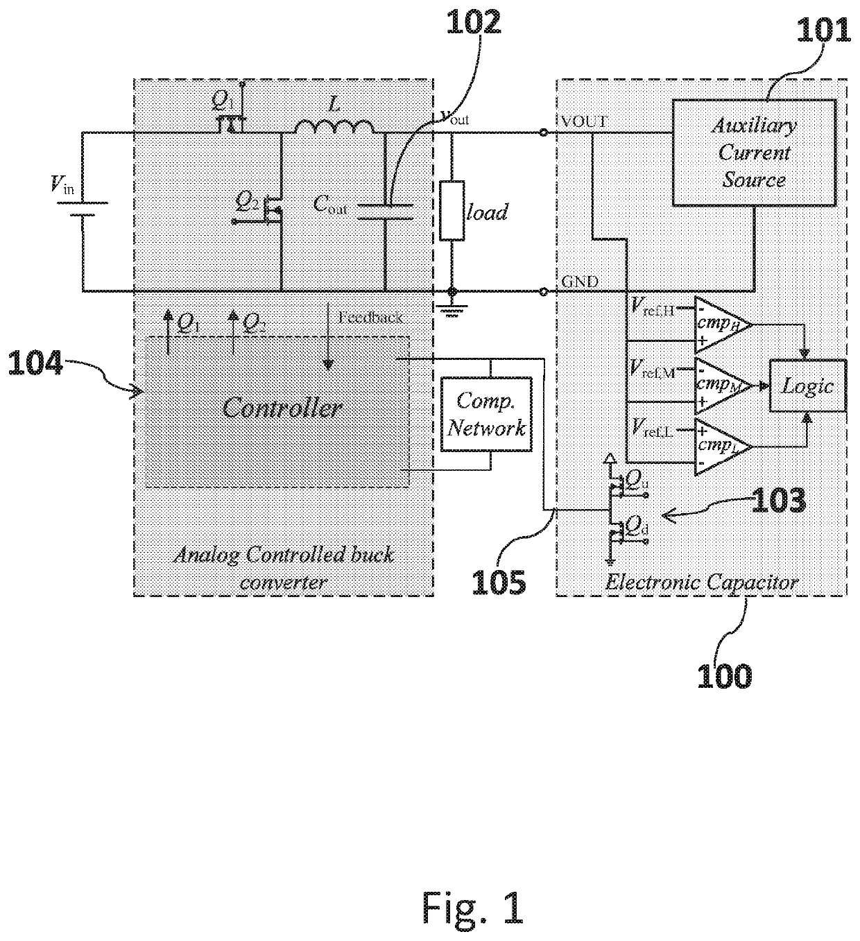
[0067]FIG. 1 shows a block diagram of the electronic capacitor circuit connected to a buck converter. As shown in FIG. 1, TSU 100 comprises a bi-directional current source 101 that connects in parallel to the buck converter's output capacitor 102, and a transient response accelerator 103 that connects in parallel to the output of the error-amplifier 104. Since the Electronic Capacitor 100 is active only during load transients, the steady-state precision is not jeopardized and the design procedure for the buck converter remains intact.

[0068]In various embodiments, current source 101 can be implemented by a Gyrator Resonant Switched-Capacitor Converter (GRSCC) as described in W...


PUM


Abstract

A plug-and-play Transient Suppression Unit (TSU) for Voltage Regulator Modules (VRMs), which comprises a bi-directional current source connected via a high voltage port and a low voltage port of the TSU in parallel to a voltage output of the VRM, adapted to immediately sink or source current supplied to a load; a detection circuit for detecting mismatches between the voltage output of the VRM to a reference steady-state voltage, which comprises a first comparator for detecting a match between the voltage output of the VRM to the reference steady-state voltage; a second comparator for detecting a mismatch between the voltage output of the VRM to a predefined threshold higher than the reference steady-state voltage; a third comparator for detecting a mismatch between the voltage output of the VRM to a predefined threshold lower than the reference steady-state voltage value; a transient response accelerator, connected via a third port of the TSU to the output compensation port of the VRM error amplifier, and adapted to control duty-ratio saturation of the VRM. A loading transient is detected by the third comparator, upon which the VRM's duty ratio is saturated to a maximal value by the transient response accelerator and current is sourced from the current source to the output, until the first comparator detects that the voltage output of the VRM matches the expected steady-state voltage. An unloading transient is detected by the second comparator, upon which the VRM's duty ratio is saturated to a minimal value by the transient response accelerator and current is sunk from the output into the current source, until the first comparator detects that the voltage output of the VRM matches the expected steady-state voltage.

Description

FIELD OF THE INVENTION[0001]The present invention relates to the field of Voltage Regulator Modules (VRMs). More particularly, the invention relates to a capacitor-like Transient Suppression Unit (TSU) to enhance the performance and reduce the overall volume of VRMs, especially reducing the value and volume of the physical output capacitance required at the output of the VRM to sustain load transients within defined boundaries.BACKGROUND OF THE INVENTION[0002]A target feature in present-day Voltage Regulator Modules (VRMs) is the ability to maintain a well-regulated, virtually constant, output voltage under a wide range of load changes while maximizing power density. A key consideration to achieve this goal is the physical size of the passive components that prohibits full integration of the solution. Various modern applications raise the switching frequency and employ multi-phase converters to enhance the transient response that allow integration of an inductor. On the other hand, ...

Claims


Application Information

Patent Timeline
Patent Type & Authority Patents(United States)
IPC IPC(8): H02M3/158H02M3/156H02M1/00
CPCH02M3/158H02M2001/0025H02M2003/1566H02M3/1588Y02B70/10H02M1/0025H02M3/1566
Inventor PERETZ, MOR MORDECHAICERVERA, ALONKIRSHENBOIM, OR
Owner B G NEGEV TECH & APPL LTD
Features
  • R&D
  • Intellectual Property
  • Life Sciences
  • Materials
  • Tech Scout
  • Unparalleled Data Quality
  • Higher Quality Content
  • 60% Fewer Hallucinations
Learn More