
Developing device and image forming apparatus having developer replenishing blade

a development device and developer technology, applied in the direction of electrographic process equipment, instruments, optics, etc., to achieve the effect of suppressing developer compaction

Active Publication Date: 2021-02-16
FUJIFILM BUSINESS INNOVATION CORP
View PDF5 Cites 0 Cited by
  • Summary
  • Abstract
  • Description
  • Claims
  • Application Information

AI Technical Summary

Benefits of technology

This patent is about a new type of stirring member used in a developing device to move developer. The main advantage of this new design is that it reduces the chance of the developer getting compacted compared to a different design that only has a reverse spiral blade. This helps to keep the developer moving smoothly through the device and improves its overall quality.

Problems solved by technology

However, aspects of the non-limiting embodiments are not required to address the advantages described above, and aspects of the non-limiting embodiments of the present disclosure may not address advantages described above.

Method used


Image

  • Developing device and image forming apparatus having developer replenishing blade
  • Developing device and image forming apparatus having developer replenishing blade
  • Developing device and image forming apparatus having developer replenishing blade

Examples


Embodiment Construction

[0014]An exemplary embodiment for implementing the present disclosure (hereinbelow, this exemplary embodiment) will be described below. In the description below, arrows H, W, and D in the drawings represent the top-bottom direction (vertical direction), the width direction (horizontal direction), and the depth direction (horizontal direction).

[0015]An example developing device and an example image forming apparatus according to this exemplary embodiment will be described with reference to FIGS. 1 to 6.

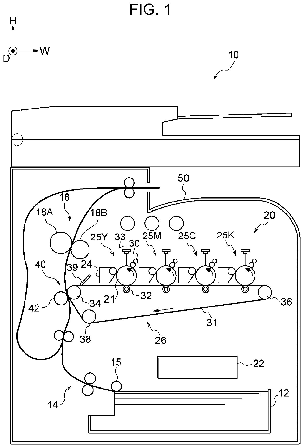
[0016]FIG. 1 illustrates an example configuration of an image forming apparatus including developing devices according to the exemplary embodiment of the present disclosure. As illustrated in FIG. 1, an image forming apparatus 10 includes: a sheet storage part 12 that stores sheets P, serving as an example of media; a transport unit 14, a toner-image forming section 20, a fixing device 18, an output part 50, and a controller 22. The toner-image forming section 20 includes four image fo...


PUM


Abstract

A developing device includes: a housing having a first transport path through which developer is supplied, a second transport path adjoining the first transport path with a first partition wall therebetween, and a first communication path communicating with the second transport path on a downstream side in a developer transport direction in the first transport path; a first transport member disposed in the first transport path and having an axially rotatable first rotary shaft and a first spiral blade projecting from an outer circumferential surface of the first rotary shaft; a second transport member disposed in the second transport path and having an axially rotatable second rotary shaft and a second spiral blade projecting from an outer circumferential surface of the second rotary shaft; and a first blade member projecting from the outer circumferential surface of the first rotary shaft, at a position facing the first communication path, the blade member discharging the developer onto the second transport path from above the first rotary shaft in the first transport path with the rotation of the first rotary shaft.

Description

CROSS-REFERENCE TO RELATED APPLICATIONS[0001]This application is based on and claims priority under 35 USC 119 from Japanese Patent Application No. 2019-166541 filed Sep. 12, 2019.BACKGROUND(i) Technical Field[0002]The present disclosure relates to a developing device and an image forming apparatus.(ii) Related Art[0003]Japanese Unexamined Patent Application Publication No. 2016-024255 discloses a developing device including: a developer container having multiple developer transport paths disposed substantially parallel to one another, and communicating portions provided at both ends of the developer transport paths, through which the developer is transferred; a developer carrier that carries the developer on the surface thereof and that is supported by the developer container so as to be rotatable; and stirring / transporting members disposed in the developer transport paths to transport, while stirring, the developer in the longitudinal direction. At least one stirring / transporting ...

Claims


Application Information

Patent Timeline
Patent Type & Authority Patents(United States)
IPC IPC(8): G03G15/08
CPCG03G15/0893G03G15/0808G03G15/0889G03G15/0887G03G15/0891G03G2215/083G03G2215/0833
Inventor TAMAZAWA, NORIHIROOZAKI, YOSHIFUMIKURAMOTO, SHINICHINAKAJIMA, YOSHITAKAYOSHII, TOMOYUKI
Owner FUJIFILM BUSINESS INNOVATION CORP
Learn More