In-situ barrier device with internal injection conduit

a barrier device and conduit technology, applied in shaft equipment, shaft lining, mining structures, etc., can solve the problems of requiring enormous preparation work on site, and achieve the effect of fast and convenient installation

Active Publication Date: 2021-07-27
GCP APPL TECH INC
View PDF90 Cites 0 Cited by
  • Summary
  • Abstract
  • Description
  • Claims
  • Application Information

AI Technical Summary

Benefits of technology

[0006]In surmounting the deficiencies of the prior art, the present invention provides a multi-layer device that enables faster and more convenient installation of a grout wall system, and particularly for establishing a grout wall using an assembly of such multi-layer devices.
[0010]While the invention contemplates that the multi-layer device can be assembled from separate components at the construction site, the inventors believe that it is more convenient, efficient, and faster to use pre-assembled multi-layer devices, so that installation effort and time are minimized. In either case, one creates an “in situ” (or “in place”) barrier system that defines a confined flow area for injection fluids such as waterproofing resins and grouts.
[0011]The present invention has particular value in vertical wall applications, especially for sealing to prevent leakages at cold joints, as defined between concrete floors and subsequently poured vertical walls. The device is assembled or installed as a pre-assembled unit against a substrate (e.g., excavation, existing wall or foundation, formwork or mold, tunnel wall, etc.), and, subsequently, concrete is cast or sprayed against its outward-facing layer. The device may also be assembled or installed in horizontal applications, such as sub-layer or subflooring for concrete slabs, decks, and floor applications, including applications where the existence and location of joints and segment dimensions are not predictable or uniform. In either horizontal or vertical applications, the devices and assemblies of the invention can protect against moisture penetration due to crack formations or other leakage pathways formed within or between concrete structures.
[0013]The present invention also has particular value in shotcrete applications, wherein concrete is sprayed against the outward face of the device. When the device of the invention is installed against a wall, and concrete is poured or spray-applied against rebar adjacent the installed device, the device will allow a subsequently injected resin or grout to permeate through the outward face porous layer and fill in “shadow” areas where the rebar interrupts the path of the poured or sprayed concrete (or shotcrete), thereby creating a full contact seal with the concrete (or shotcrete).
[0014]In other embodiments, the barrier devices of the present invention having the at least one injection conduit member in parallel orientation with respect to the first and second layers are provided in rollable or stacked form that can be used conveniently and quickly at the construction site. In other words, two or more pre-assembled multi-layer fluid delivery units can be connected together to form a monolithic barrier layer wherein their at least one injection conduit member(s) are connected to permit an injection fluid (e.g., grout, resin, cement) to be pumped through and / or into several barrier devices at once, thereby creating a monolithic water-resistive curtain over an area that is larger than an individual barrier device. The concrete which is subsequently cast or sprayed against the installed barrier devices allow the in-situ barriers to stay in place during fluid injection, and to resist the compressive pressure required to inject the fluid into the open-matrix intermediate layer and through the permeable outward porous (e.g., woven or nonwoven) fabric which comprises the outward face layer.
[0018]The present invention avoids the inconvenience of having to install numerous injection tubes extending perpendicularly across the outward face of the device, as well as the inconvenience of applying concrete around the perpendicularly extending tubes.

Problems solved by technology

The present inventors believe that such prior art multi-layer grout wall devices, due to the large number of perpendicularly extending tubes or pipes, required enormous preparation work on site, even when the devices were installed as pre-assembled integral units.

Method used


Image

  • In-situ barrier device with internal injection conduit
  • In-situ barrier device with internal injection conduit
  • In-situ barrier device with internal injection conduit

Examples


Embodiment Construction

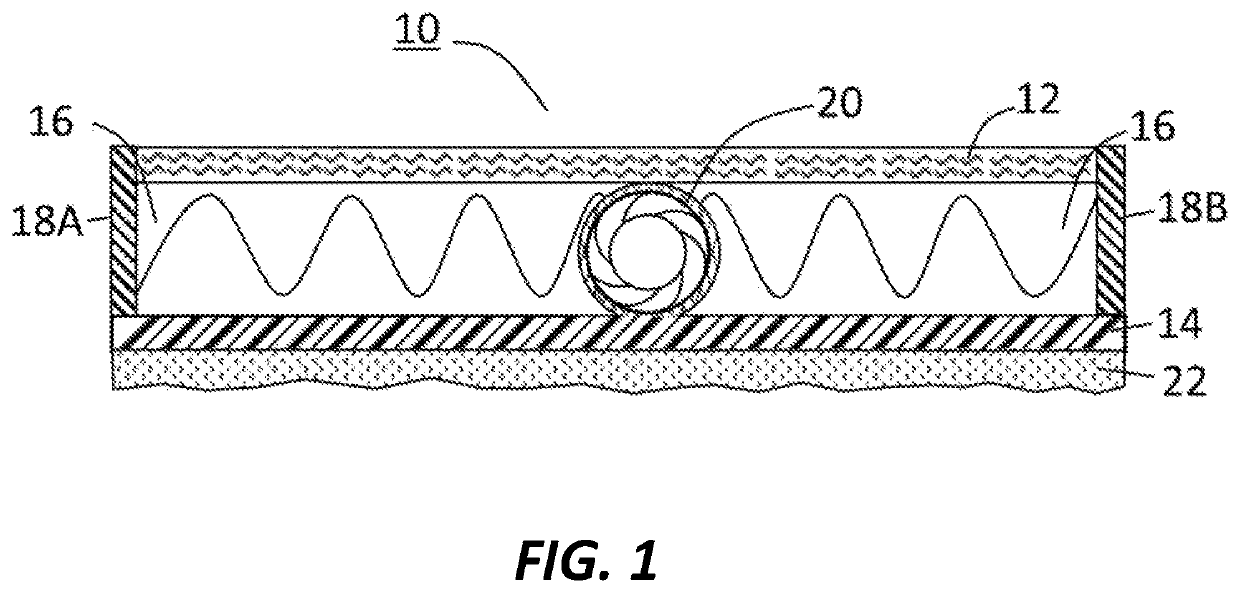
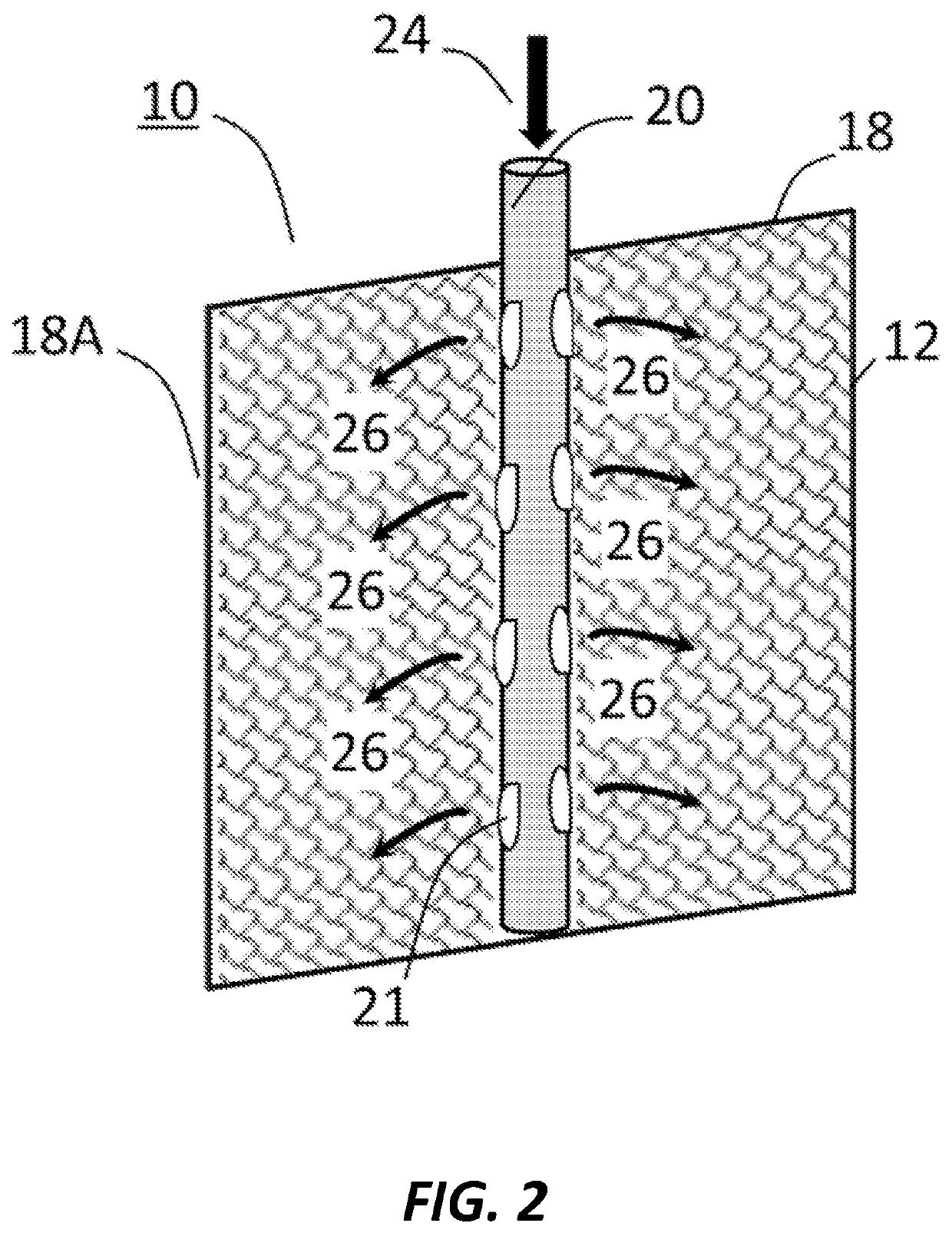
[0038]The present invention relates to a multi-layer assembly or device for a post-installation in-situ barrier, as well as a method for assembling the barrier, using one or more injection conduit members that are parallel to the major faces or layers of the assembly or device, in contrast to the prior art use of perpendicularly extending pipes as taught by Iske et al. as mentioned in the Background section.

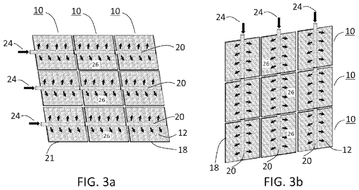
[0039]The terms “assembly” and “device” may be used interchangeably throughout this specification. Ideally, relatively little assembly of an individual multi-layer device is required at the construction site, although the establishment of a grout wall against concrete that is poured or sprayed against a number of such individual multi-layer devices will require some “assembly” to join individual multi-layer devices together, including injection conduit members to permit filling two or more of the devices using a single source of injection fluid. (This will be described further he...


PUM

PropertyMeasurementUnit
thicknessaaaaaaaaaa
widthaaaaaaaaaa
lengthaaaaaaaaaa

Abstract

The present invention provides a multi-layer barrier assembly or device for post-installation injection of a resin, grout, or other fluid. The barrier device comprises first and second layers defining an intermediate open-matrix layer, and at least one injection conduit member in parallel orientation with respect to the first and second layers and having openings for injecting fluid into the intermediate open-matrix layer. The injection conduit may be located between and in parallel orientation with respect to the first and second layers, along an edge of the first and / or second layers, along an outer face of the first layer (if the first layer is a woven or nonwoven fabric), or at any combination of these locations, to enable fluid to be conveyed into the intermediate open-matrix layer. The invention also provides for use of a gel activator within the barrier device cavity, such as pre-installed on open-matrix structure which used for separating the first and second layers of the barrier device, such that a highly flowable injection fluid can be introduced into the device, and its gelation or hardening will be initiated or accelerated by the presence of the gel activator. This will allow for low power grout pumps to be used and facilitate the sealing of fine cracks in the surrounding concrete.

Description

FIELD OF THE INVENTION[0001]The invention relates to a barrier device for post-installation injection of a waterproofing fluid; and, more particularly, to a multi-layer device having first and second layers defining an intermediate open-matrix layer, and at least one injection conduit member disposed in parallel orientation with respect to the first and second layers to permit a waterproofing fluid to be injected into the open-matrix layer. The at least one injection conduit member may be located between the first and second layers and thus within the open matrix layer, at the edge of the multi-layer device and adjacent to an open matrix layer, along an outer face of the first layer if the first layer is made of nonwoven or woven fabric, or combination of these locations, whereby an injection fluid can be conveyed through the conduit member and into the open matrix layer.BACKGROUND OF THE INVENTION[0002]The use of multi-layer devices for post-installation, in-situ creation of barrie...

Claims


Application Information

Patent Timeline
Patent Type & Authority Patents(United States)
IPC IPC(8): E21D11/38E02D19/18E02D31/02
CPCE21D11/381E02D19/18E02D31/02E21D11/383E02D2250/003E02D2300/002E02D2300/0025E02D2300/0076E02D2300/0078E02D31/04E21D11/38
Inventor HYDER, MD NASIMWIERCINSKI, ROBERT A.SETH, JYOTIAUSTIN, GREGFORGEY, CHRISTIAN A.DSILVA, SEAN
Owner GCP APPL TECH INC
Why Eureka
Try Eureka