
Orthodontic band attachment device

a technology of orthodontic band and attachment device, which is applied in the field of dental appliances, can solve the problems of inconvenient use, increased discomfort or risk of complications for patients, and the device of this reference lacks the functionality of a button and a hook

Active Publication Date: 2022-02-15
KING ABDULAZIZ UNIV
View PDF19 Cites 4 Cited by
  • Summary
  • Abstract
  • Description
  • Claims
  • Application Information

AI Technical Summary

Benefits of technology

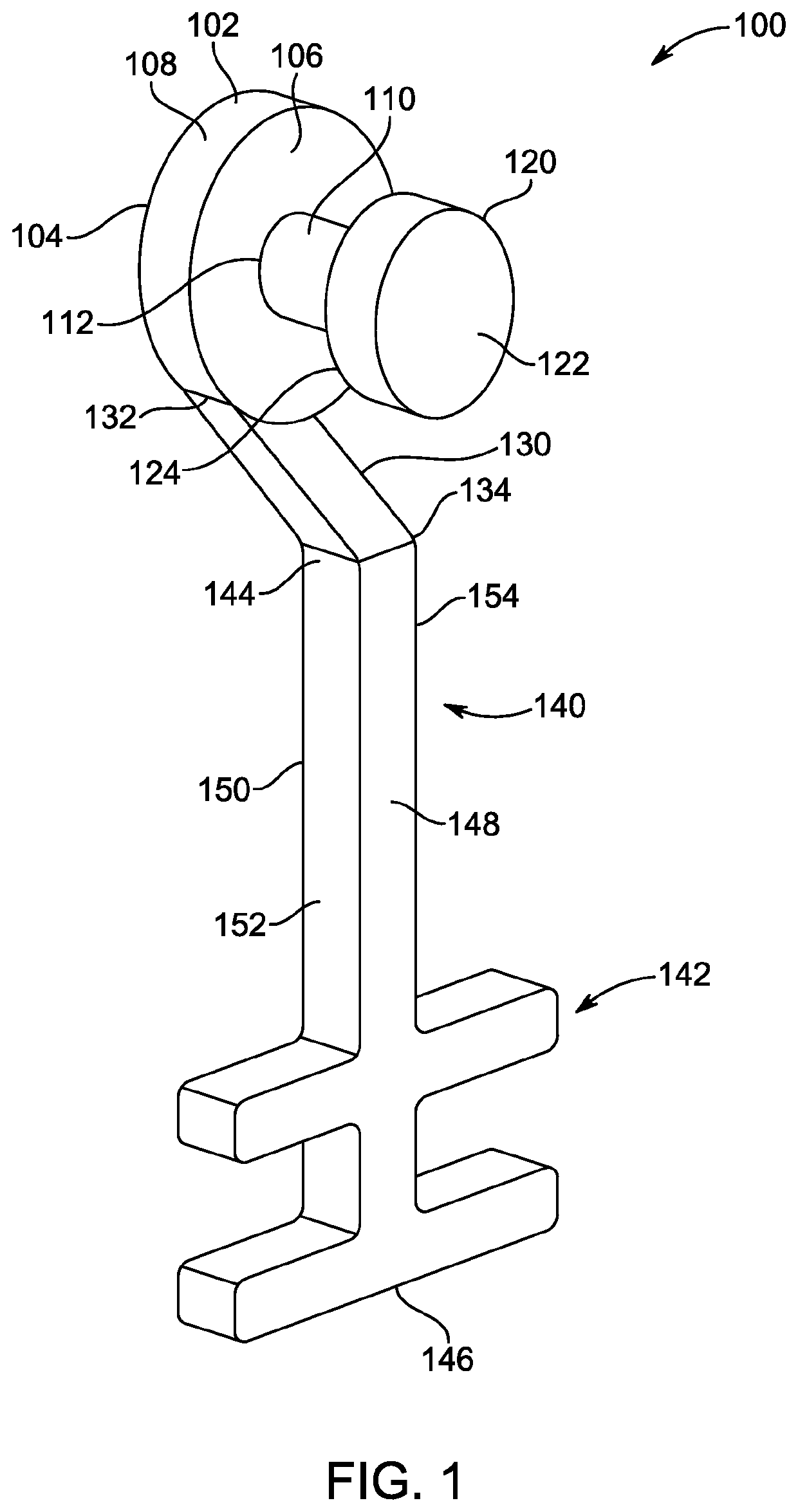
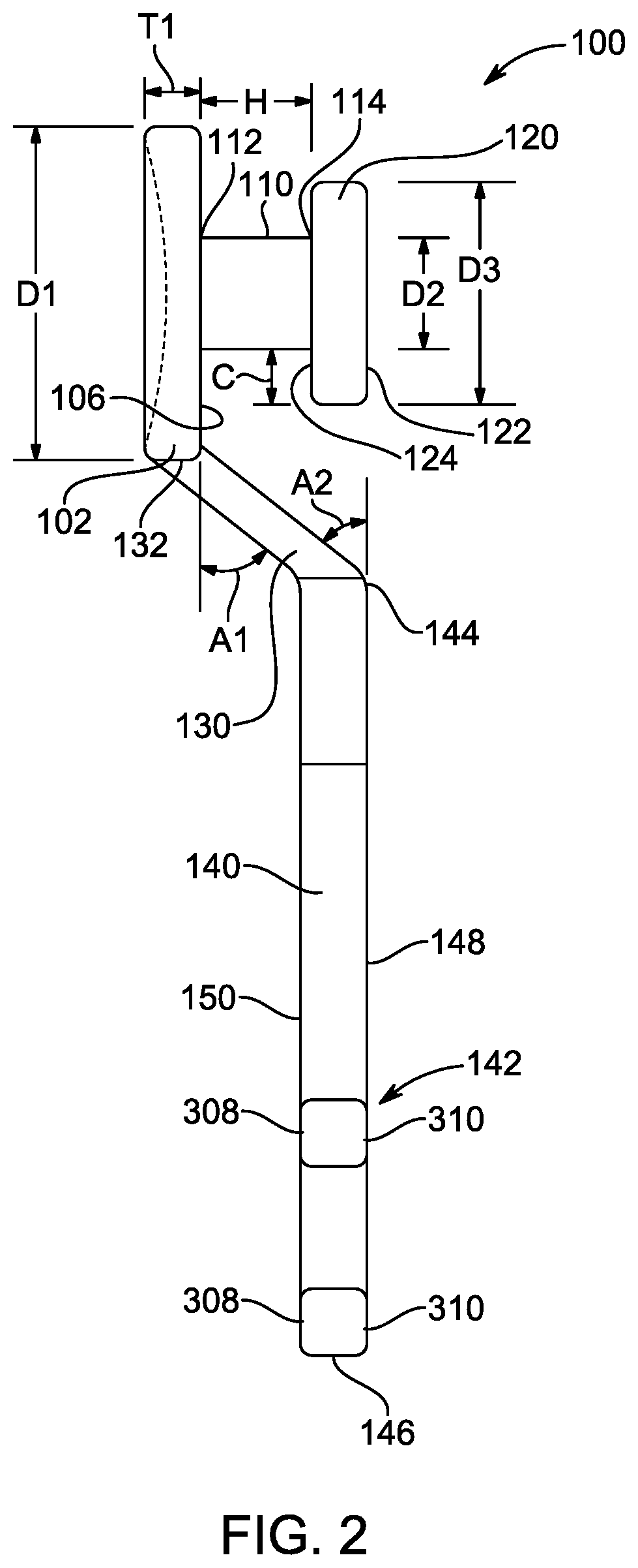
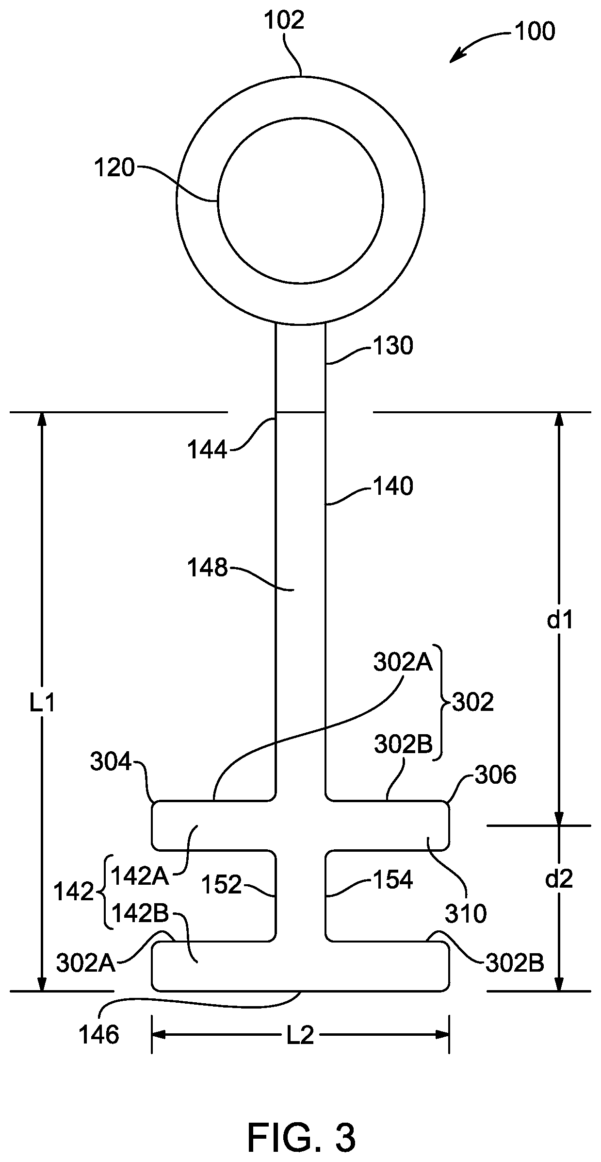
The orthodontic band attachment device described in this patent allows for the secure attachment of orthodontic bands to teeth. The device includes a base with a tooth interfacing surface and an outer base surface, as well as a button support column and a hook arm attachment member. The button support column is smaller than the outer base surface and has a button support column diameter and a button support column height. The device also includes a button structure with a button support column diameter and an inner button surface attached to the button support column. The hook arm attachment member is attached at a peripheral location and includes one or more band attachment structures along its length with a hook arm outer surface and inner surface. The button overhang distance is at least 0.25 mm. The tooth interfacing surface is concaved, contoured, or has an adhesive accommodating texture. The base is circular. The button support column height is at least 0.5 mm. The hook arm angle is at least 30 to 60 degrees with respect to the hook arm attachment member. The band attachment structure includes a band attachment projection and band attachment indentation or a band securing projection. The outer button surface and hook arm outer surface are convex. The technical effects of this device include secure attachment of orthodontic bands to teeth, improved aesthetics, and ease of use.

Problems solved by technology

For example, during space closure in extraction cases, forces applied through brackets are away from the center of rotation of the teeth which is not helpful in space closure to aid in roots movement.
Having to remove a first orthodontic device and either move it or replace it with a second device can be costly, time-consuming, and cause a patient increased discomfort or increased risk of complications.
However, the device of this reference lacks the functionality of a button combined with the hook.
However, the power arm disclosed in this reference lacks functionality of button and hook combined with a single device.
However, the elastic attachment of this reference does not have the functionality of hook combined with that of the button.
Further, the force caused by the band attached to the pull hooks or the protrusions and the force caused by the band attached to the connecting piece or the seating part together act on the bottom plate or the tooth fixing part which may impact attachment of the device with the tooth surface and may make the bonding weak over a period of time.
Further, such arrangement may place large amounts of torque on the connecting piece or the seating part when the elastic bands or other structures are attached to the hooks.
These factors may lead to increased risk of device failure, possibly creating an uncomfortable or dangerous situation for a patient.
Each of the aforementioned patent references suffers from one or more drawbacks which makes their use disadvantageous.

Method used


Image

  • Orthodontic band attachment device
  • Orthodontic band attachment device
  • Orthodontic band attachment device

Examples


Embodiment Construction

[0037]In the drawings, like reference numerals designate identical or corresponding parts throughout the several views. Further, as used herein, the words “a,”“an” and the like generally carry a meaning of “one or more,” unless stated otherwise.

[0038]Furthermore, the terms “approximately,”“approximate,”“about,” and similar terms generally refer to ranges that include the identified value within a margin of 20%, 10%, or preferably 5%, and any values there between.

[0039]Aspects of the present disclosure are directed to the Mahawi Orthodontic ButtonHook, an orthodontic band attachment device having a button structure with a hook arm used as an adjunctive aid for orthodontic treatment. The Mahawi Orthodontic ButtonHook includes a circular base having a tooth interfacing surface with a texture or pattern to accommodate adhesive and thereby to securely interface the device with a tooth surface. A button support column extends from the base to attach with the button structure. From the bas...


PUM


Abstract

An orthodontic band attachment device used for an orthodontic procedure is described. The device includes a base having a tooth interfacing surface and an outer base surface. The device further includes a button support column attached to the outer base surface, and a button structure attached to the button support column such that an inner button surface is separated from the outer base surface by a button support column height. The device further includes a hook arm attachment member attached to the base at a substantially peripheral location and a hook arm comprising one or more band attachment structures arranged along a hook arm length. The hook arm attachment member is oriented such that a hook arm outer surface is substantially coplanar with an outer button surface and an orthodontic band is able to pass between the hook arm attachment member and the button structure.

Description

STATEMENT OF ACKNOWLEDGEMENT[0001]The inventors extend their appreciation to the Deputyship for Research and Innovation, Ministry of Education in Saudi Arabia for funding this research work through the project number 2020-025 and King Abdulaziz University, DSR, Jeddah, Saudi Arabia.BACKGROUNDTechnical Field[0002]The present disclosure is directed to a dental appliance, and particularly, to an orthodontic band attachment device used to attach orthodontic elastics in different configurations during orthodontic procedure.Description of Related Art[0003]The “background” description provided herein is for the purpose of generally presenting the context of the disclosure. Work of the presently named inventors, to the extent it is described in this background section, as well as aspects of the description which may not otherwise qualify as prior art at the time of filing, are neither expressly or impliedly admitted as prior art against the present invention.[0004]Orthodontic procedures are...

Claims


Application Information

Patent Timeline
Patent Type & Authority Patents(United States)
IPC IPC(8): A61C7/36A61C7/16
CPCA61C7/36A61C7/16
Inventor ALQAHTANI, HAMAD
Owner KING ABDULAZIZ UNIV
Learn More