Aircraft door with sliding decompression panel

a technology of decompression panel and aircraft door, which is applied in the direction of aircraft indicators, aircraft accessories, fuselages, etc., can solve the problems of heavy weight and complex manufacture of known technology, and achieve the effects of reducing weight and complexity, preventing unwanted movement of the decompression panel, and reducing the complexity of design, weight and cos

Active Publication Date: 2022-04-05
SAFRAN CABIN INC
View PDF9 Cites 0 Cited by
  • Summary
  • Abstract
  • Description
  • Claims
  • Application Information

AI Technical Summary

Benefits of technology

[0011]In the present invention, the decompression panel is nested in the flight deck door panel so to prevent the decompression panel opening under a non-decompression scenario such as a bullet strike or blunt force intrusion. In the present invention, the decompression panel, during normal aircraft operating conditions, is nested into or received in a cavity or bracket. This nesting locks the decompression panel into place and prevents unwanted movement of the decompression panel. Under a rapid decompression event, the decompression panel portion is released by a pressure sensitive latch (referred to herein generally as a decompression sensor) and retracts or slides downwardly from or within the cavity or bracket that encloses it. The varying pressures between the passenger cabin and the flight deck then rotates the decompression panel open allowing cabin and flight deck pressure to equalize. The downward release of the decompression panel allows the present invention to reduce weight and complexity compared to the prior art because it does not require additional armoring to prevent a ballistic threat at the gap (e.g, hinge) between the door panel and the decompression panel. Due to the nesting feature, there is no gap because the panel is nested within the door. The absence of a gap means that no additional armoring is needed to prevent a ballistic threat from penetrating the gap and entering the flight deck of the aircraft. Compared to the prior art, this reduces part count, complexity of design, weight and cost.

Problems solved by technology

However, this known technology is heavy and complex to manufacture.

Method used


Image

  • Aircraft door with sliding decompression panel
  • Aircraft door with sliding decompression panel
  • Aircraft door with sliding decompression panel

Examples


Embodiment Construction

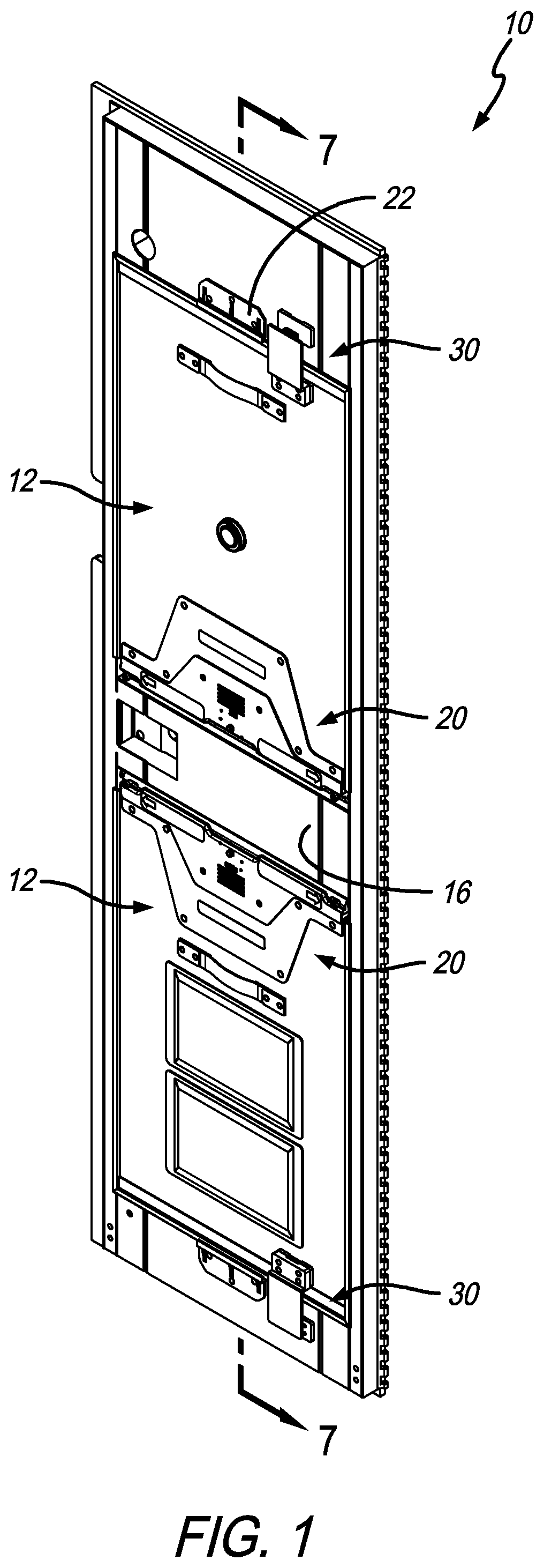
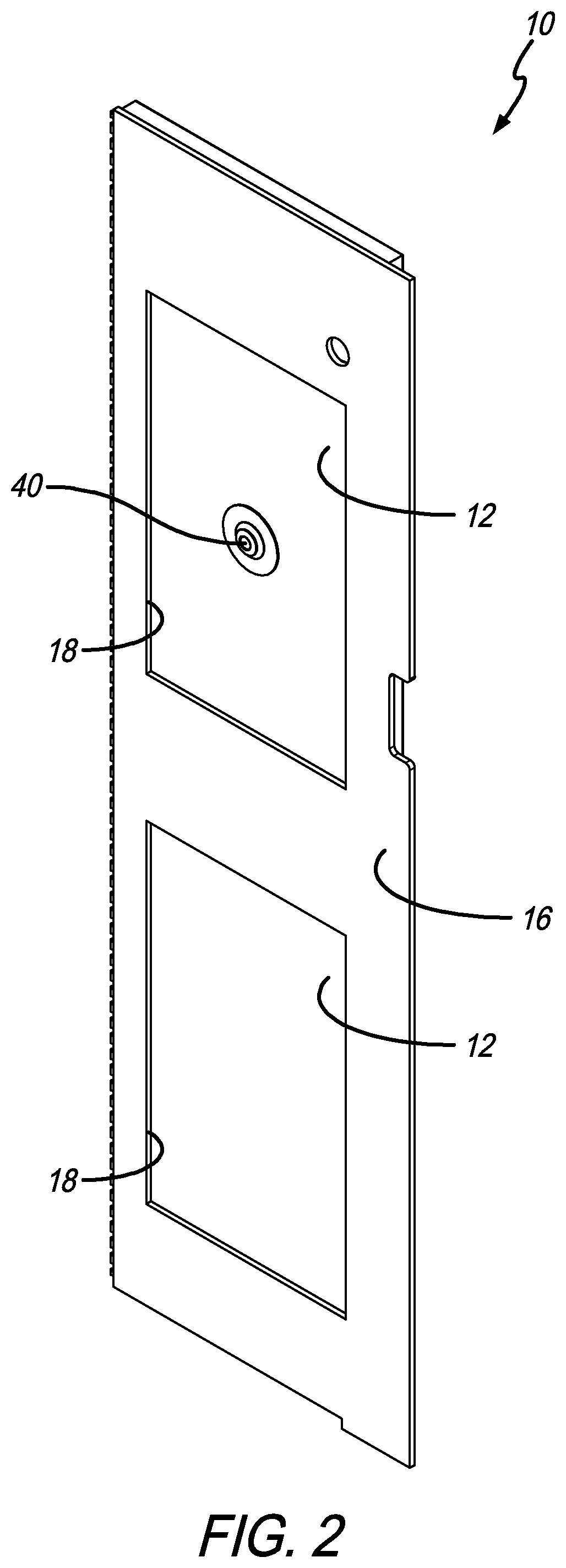
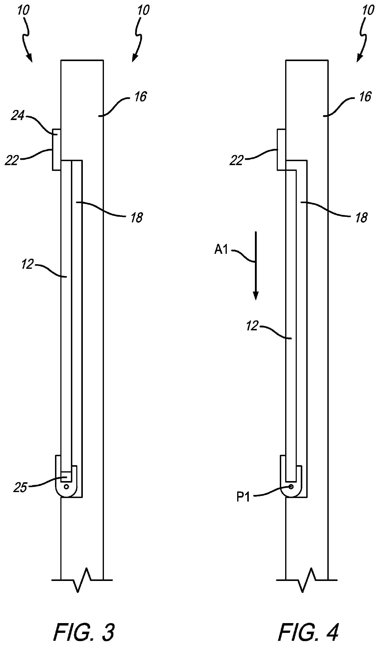
[0004]In accordance with a first aspect of the present invention there is provided a door assembly configured to be positioned between a first compartment and a second compartment that includes a main door portion having a first decompression opening defined therein, at least a first panel portion positioned in a first position within the first decompression opening, and a decompression sensor. The first panel portion is movable linearly between the first position and a second position and is pivotable between the second position and a third position. In the third position the first compartment is in fluid communication with the second compartment via the first decompression opening. In a preferred embodiment, the first panel portion is configured to move from the first position to the second position when the decompression sensor senses a decompression event. Preferably, the first panel portion includes a free end and a pivot end. In the first position a gap is defined between the ...


PUM


Abstract

A door assembly configured to be positioned between a first compartment and a second compartment that includes a main door portion having a first decompression opening defined therein, at least a first panel portion positioned in a first position within the first decompression opening, and a decompression sensor. The first panel portion is movable linearly between the first position and a second position and is pivotable between the second position and a third position. In the third position the first compartment is in fluid communication with the second compartment via the first decompression opening.

Description

CROSS REFERENCE TO RELATED APPLICATIONS[0001]This application is a national stage application, filed under 35 U.S.C. § 371, of International Patent Application No. PCT / US19 / 16111, filed on Jan. 31, 2019, which claims the benefit of U.S. Provisional Application No. 62 / 760,144, filed Nov. 13, 2018, the entireties of which are incorporated herein by reference.FIELD OF THE INVENTION[0002]The present invention relates generally to an armored aircraft door, and more particularly to an armored aircraft door with a slidable and rotatable decompression panel.BACKGROUND OF THE INVENTION[0003]The need has arisen to develop a decompression panel for an aircraft flight deck door that is preferably lighter and simpler to manufacture than the prior art. Commercial aircraft flight deck doors are required to provide a certain level of ballistic and intrusion threat resistance per FAA requirements. Flight deck doors are required to be compliant with decompression events during flight by either stayin...

Claims


Application Information

Patent Timeline
Patent Type & Authority Patents(United States)
IPC IPC(8): B64C1/14B64D45/00B64C1/00
CPCB64C1/1469B64D45/0028B64C2001/009
Inventor SATTAYATAM, PANADETANG, HAI V.
Owner SAFRAN CABIN INC
Why Eureka
Try Eureka