
Evaluation device, evaluation method, and camera system

a technology of evaluation device and luminance, which is applied in the direction of color television details, television system details, television systems, etc., can solve the problems of difficult to appropriately adjust the luminance level only by human sense, and difficulty in setting a reference for keeping the luminance level constant, so as to facilitate and appropriately evaluate the luminance of hdr video signals

Active Publication Date: 2022-10-25
SONY CORP
View PDF24 Cites 0 Cited by
  • Summary
  • Abstract
  • Description
  • Claims
  • Application Information

AI Technical Summary

Benefits of technology

This patent discusses a way for users to easily assess the brightness of HDR video signals. The technology described in the patent is not limited to this specific effect and may have additional benefits.

Problems solved by technology

However, in a case of the HDR video signal, there is a margin in an upper limit, so that it is difficult to set a reference for keeping a luminance level constant, and it is difficult to appropriately adjust a luminance level only by human sense while being affected by a surrounding environment and the like.

Method used


Image

  • Evaluation device, evaluation method, and camera system
  • Evaluation device, evaluation method, and camera system
  • Evaluation device, evaluation method, and camera system

Examples


first embodiment

1. First Embodiment

[0034][Configuration Example of Camera System]

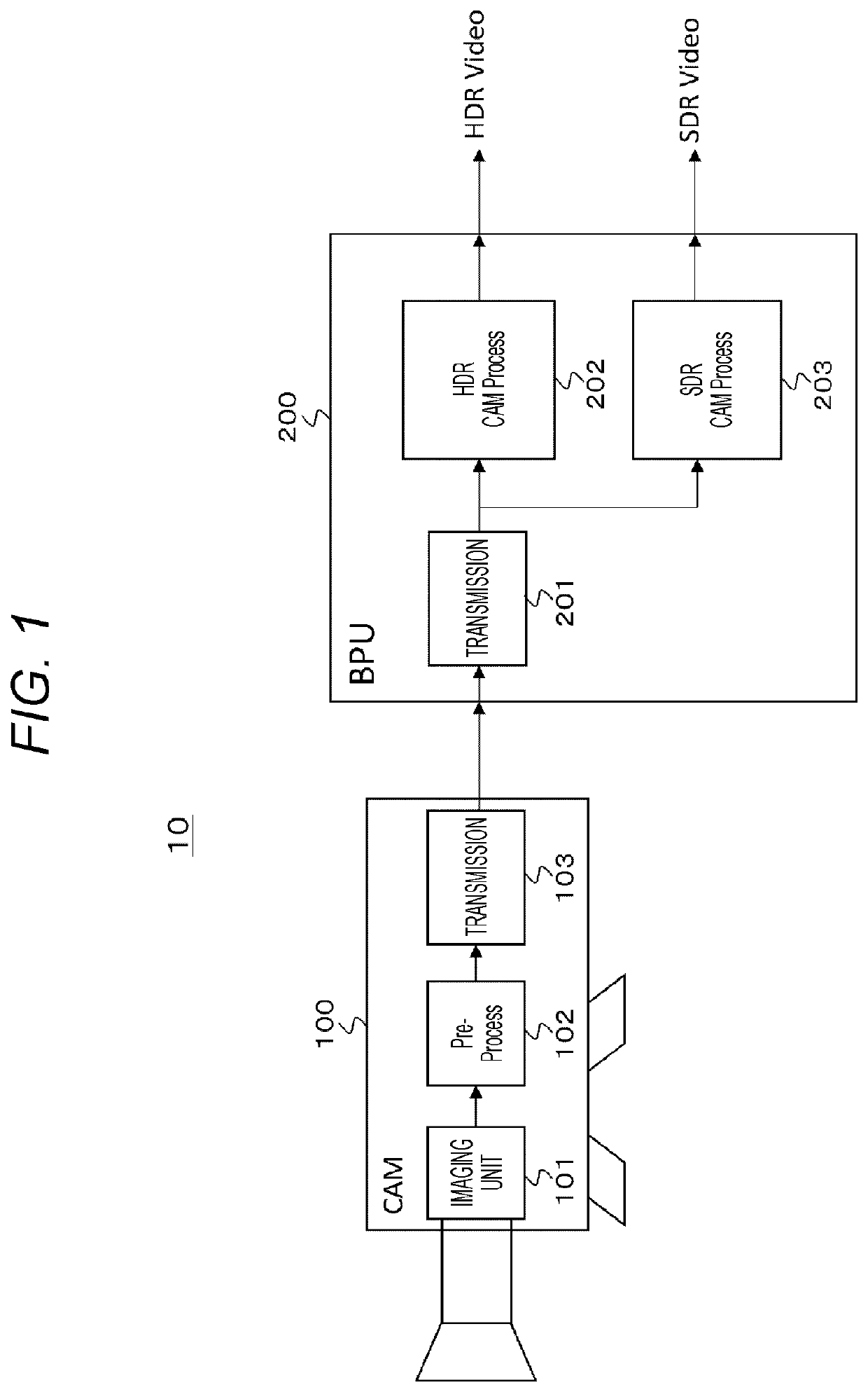
[0035]FIG. 1 illustrates a configuration example of a camera system 10 as an embodiment. The camera system 10 is configured such that a linear high dynamic range (HDR) video signal as a captured video signal obtained by a camera 100 is transmitted to a baseband processor unit (BPU) 200 as a signal processing unit. Herein, “linear” means that gradation compression processing is not performed.

[0036]The camera 100 includes an imaging unit 101, a pre-process unit 102, and a transmission unit 103. The imaging unit 101 includes, for example, an image sensor with 4K or HD resolution, and outputs an HDR video signal as the captured video signal. The pre-process unit 102 is a processor formed of a circuit such as FPGA and ASIC, for example, and performs correction processing of an optical system such as a lens, correction processing of a damage caused by variation in image sensors and the like on the HDR video signal output fro...

second embodiment

[0073][Configuration Example of Camera System]

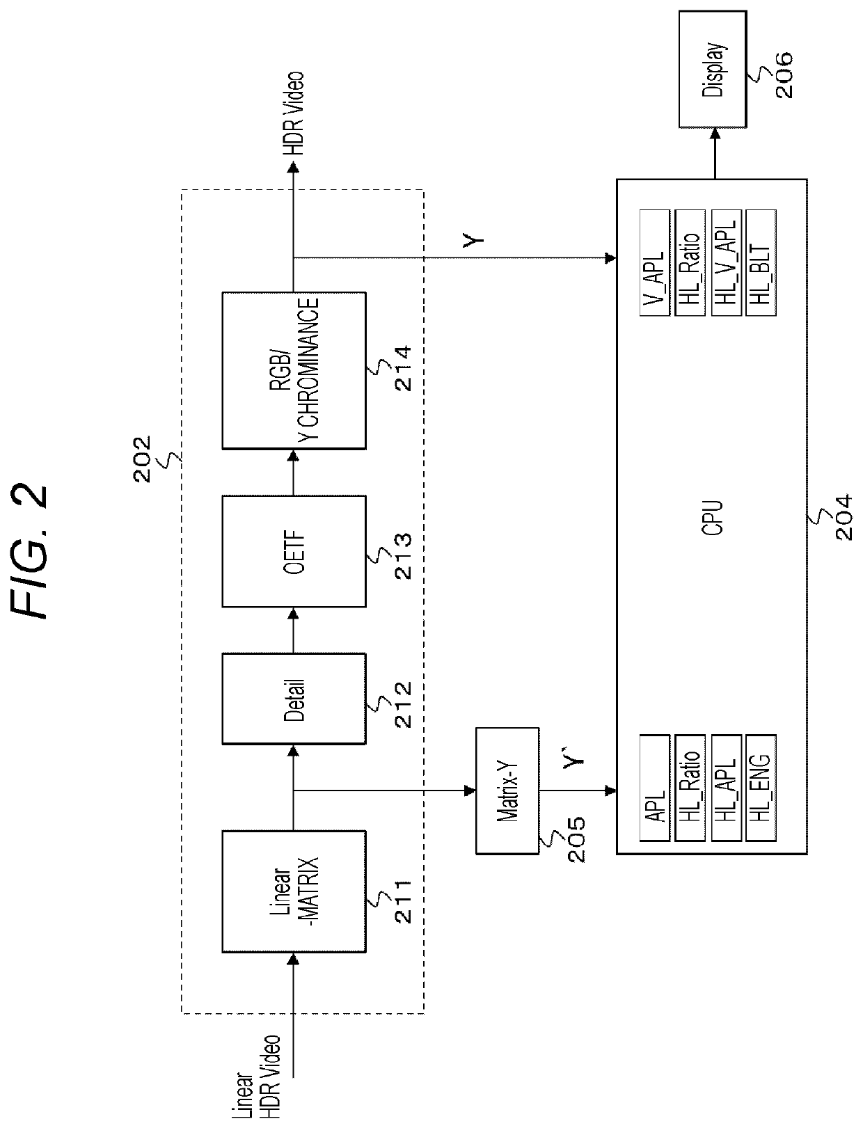
[0074]In the first embodiment described above, an example is illustrated in which a linear HDR video signal is transmitted from a camera 100 to a BPU 200 and the BPU 200 calculates to display various luminance evaluation values under supply of the linear HDR video signal. However, even in a case where the HDR video signal already subjected to gradation compression processing is supplied, similar luminance evaluation can be calculated to be displayed.

[0075]FIG. 6 illustrates a configuration example of a camera system 10A as a second embodiment. In FIG. 6, a part corresponding to that in FIG. 1 is assigned with the same reference sign, and the detailed description thereof is omitted as appropriate. The camera system 10A is configured such that the HDR video signal subjected to the gradation compression processing as a captured video signal obtained by a camera 100A is transmitted to a camera control unit (CCU) 300.

[0076]The camera 100A inc...


PUM


Abstract

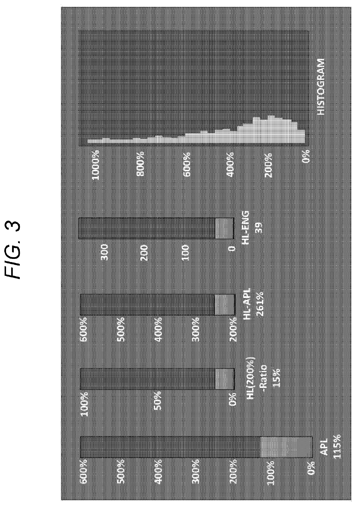
It is made such that a user can easily and appropriately evaluate luminance of an HDR video signal.A luminance evaluation value is obtained by processing the HDR video signal. The luminance evaluation value is displayed on a display unit. For example, the HDR video signal is a linear HDR video signal and / or the HDR video signal obtained by performing gradation compression on the linear HDR video signal with a log curve characteristic. For example, the luminance evaluation value includes an average picture level, a high light share ratio, a high light average picture level, a product value of the high light share ratio and the high light average picture level and the like.

Description

CROSS-REFERENCE TO RELATED APPLICATIONS[0001]This application is a continuation of U.S. Ser. No. 16 / 077,531, filed on Aug. 13, 2018, which is incorporated herein by reference. U.S. Ser. No. 16 / 077,531 is a National Stage of PCT / JP2017 / 007559, filed on Feb. 27, 2017, and claims the benefit of priority under 35 U.S.C. § 119 of Japanese Application No. 2016-042866, filed Mar. 4, 2016.TECHNICAL FIELD[0002]The present technology relates to an evaluation device, an evaluation method, and a camera system, and specifically relates to a luminance evaluation device and the like for evaluating luminance of a high dynamic range video signal.BACKGROUND ART[0003]A video signal of a high dynamic range (HDR) has a luminance level range from 0% to 100%*N (N is a number larger than one) with respect to a video signal of a standard dynamic range (SDR) having a luminance level range from 0% to 100%. A camera which outputs an HDR video signal as a captured video signal is conventionally known (refer to,...

Claims


Application Information

Patent Timeline
Patent Type & Authority Patents(United States)
IPC IPC(8): H04N5/232H04N5/235H04N5/20H04N17/00
CPCH04N5/2351H04N5/20H04N5/232939H04N17/002H04N5/2355H04N23/71H04N23/741H04N23/633
Inventor KAMIYA, KOJI
Owner SONY CORP
Learn More