Device and method for detecting movement of ejector plate

Inactive Publication Date: 2001-08-02
FUTABA CORPORATION
View PDF0 Cites 17 Cited by
  • Summary
  • Abstract
  • Description
  • Claims
  • Application Information

AI Technical Summary

Problems solved by technology

The operation continued with noticing such a phenomenon may cause a serious trouble such as a damage of a mold tool.

Method used


Image

  • Device and method for detecting movement of ejector plate
  • Device and method for detecting movement of ejector plate
  • Device and method for detecting movement of ejector plate

Examples


first embodiment

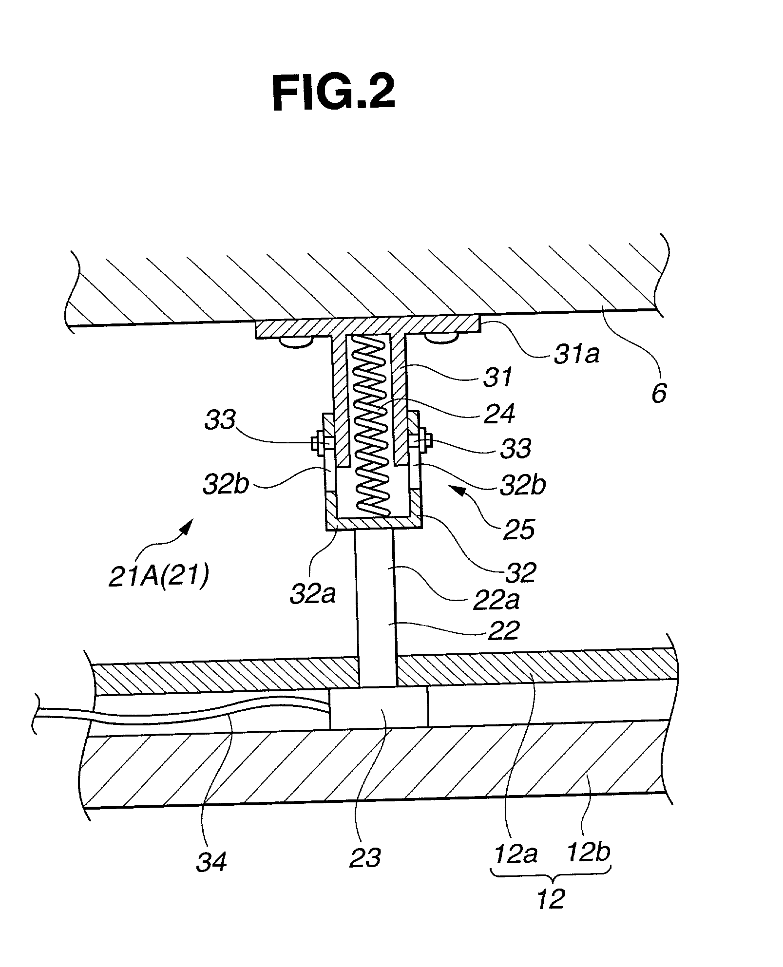
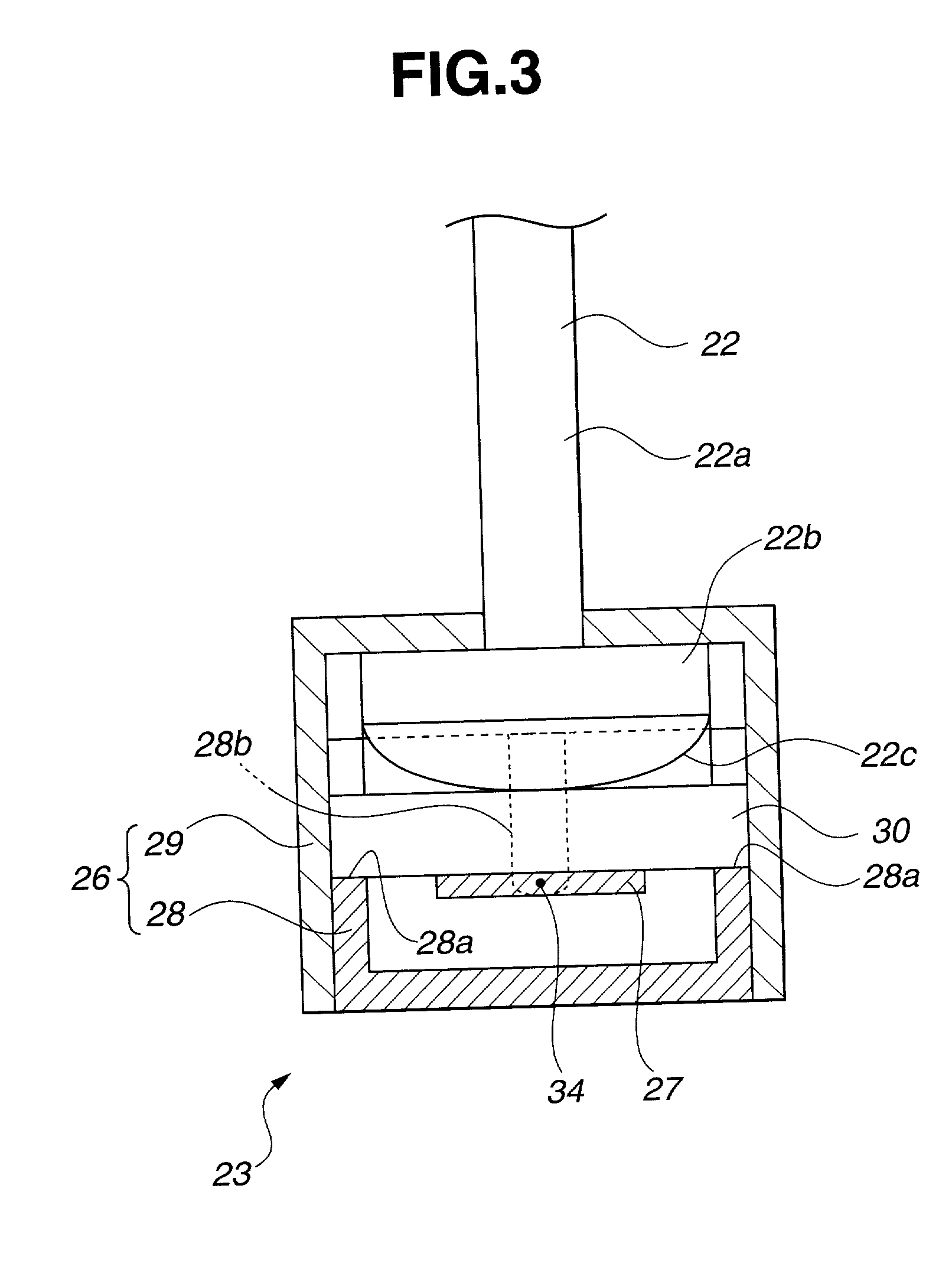
[0038] Next, FIG. 2 is a cross-sectional view illustrating an ejector plate movement detector applied to a mold tool. FIG. 3 is an enlarged cross-sectional view illustrating pressure detecting means used for an ejector plate movement detecting device.

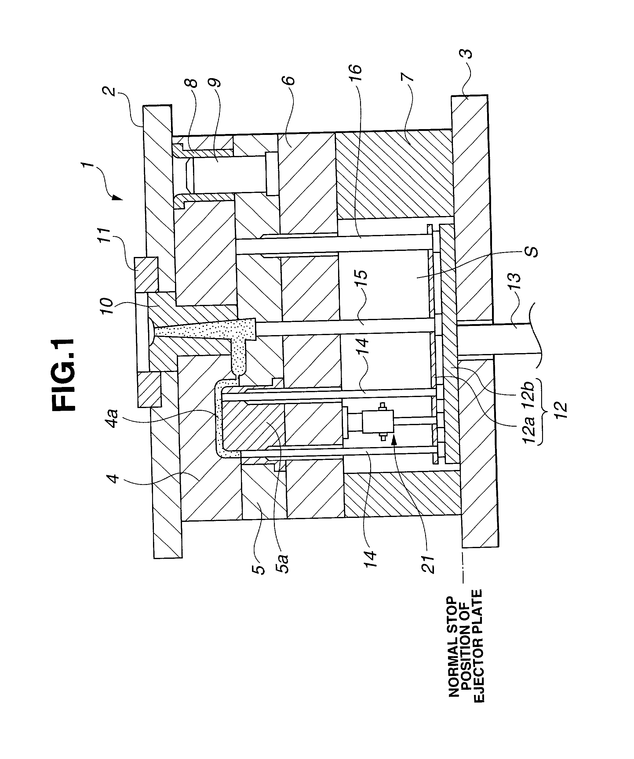
[0039] The ejector plate movement detector (hereinafter abbreviated as a detector) 21A (21) according to the first embodiment shown in FIG. 2 has a pin-like form similar to that of the ejector pin 14, 15. The detector 21A is disposed between the backing plate 6 on the movable side and the ejector plate 12.

[0040] The detector 21A consists of a rod-like pin 22, a pressure detector attached on end of the pin 22, a biasing member 24 for always applying a biasing force in the direction returning the ejector plate 12 attached to the other end of the pin 22 to the original position, and a holder for housing the biasing member 24 and movably holding the pin 22 against the biasing force of the biasing member 24.

[0041] The pin 22, as shown in FI...

second embodiment

[0055] In the detector 21A, the spring 24 acting as a biasing member is housed inside the cylinders 31 and 32 in a telescopic state. The pin 22 has the pressure detector 23. The rod-like portion of the pin 22 is in contact with the flat surface 32a of the outer cylinder 32. However, in the detector 21B (21) of the second embodiment, a single cylinder 41 acting as a holder 25 houses a spring (biasing member) 24. The rod-like portion 22a of the pin 22 is in contact with one end of the spring 24.

[0056] In further explanation, the cylinder 41 has a flange 41a which has one end fixed to the backing plate 6 by means of screws and the other end in open. Two guide pins 33 and 33 are inserted into the end of the rod-like portion 22a of the pin 22 so as to confront to each other. Each of long holes 41b, 41b is formed as equal as the stroke of the ejector plate 12 along the longitudinal direction of the cylinder 41. Screws prevent the guide pin 22 from coming out of the cylinder 41, with the g...


PUM

PropertyMeasurementUnit
diameteraaaaaaaaaa
thicknessaaaaaaaaaa
pressureaaaaaaaaaa

Abstract

An ejector plate movement detector is provided that can be mounted, without complicatedly machining a mold tool and occupying an installation place, and can detect movement of an ejector plate, with damages of parts suppressed to a necessary minimum. The detector 21A comprises a rod-like pin 22; a pressure detector 23 integrally attached on one end of the pin 22 and mounted on the ejector plate 12, for detecting the pressure applied via the pin 22 when the ejector plate 12 is moved forward and backward; a biasing member 24 for always biasing the ejector plate 12 to its original position with respect to the pin 22; and a holder 25 having one end fixedly mounted to the receiving plate 6, for housing said biasing means 24 and movably holding the pin against the biasing means 24. Whether or not the ejector plate 12 is normally moved is checked by monitoring waveforms of output values from the pressure sensor 27 before and after the movement of the ejector plate 12 at the ejection of a molded piece.

Description

[0001] 1. Field of the Invention[0002] The present invention relates to an ejector plate movement detector built in a molding metal tool (hereinafter abbreviated to mold tool), in the field of injection molding technique and the field of die-casting technique. The ejector plate movement detector detects whether or not an ejector plate has returned to its normal position after the forward and backward movement of an ejector plate caused ejector pins to push a molded piece out of a mold tool. Moreover, the present invention relates to an ejector plate movement detecting method.[0003] 2. Description of the Related Art[0004] Conventionally, a mold tool 1, as shown in FIG. 7, is used to form a desired molded piece through the injection molding. The whole configuration of the mold tool 1 will be explained later. In order to make a molded piece using the mold tool 1 shown in FIG. 7, a movable mold plate 5 with a core 5a is relatively moved toward a stationary mold plate 4 with a cavity 4a ...

Claims


Application Information

Patent Timeline
Patent Type & Authority Applications(United States)
IPC IPC(8): B22D17/22B29C33/44B29C45/40B29C45/76
CPCB29C45/4005B29C45/7626B29C2945/76006B29C2945/7611B29C2945/7624B29C2945/76244B29C2945/76481
Inventor KAWASAKI, HIROAKIISHIWATA, YASUOHIROSHIMA, YUTAKAAKINARI, CHISATO
Owner FUTABA CORPORATION
Why Eureka
Try Eureka