Magnetic head and manufacturing method therefor

a manufacturing method and head technology, applied in the field of magnetic head, can solve the problems of generating noise, difficult to form magnetic metal films facing each other on a sole substrate, and difficulty in coping with digital picture recording

Inactive Publication Date: 2001-11-22
OGATA SEIICHI +4
View PDF0 Cites 1 Cited by
  • Summary
  • Abstract
  • Description
  • Claims
  • Application Information

AI Technical Summary

Problems solved by technology

Thus, it is difficult to cope sufficiently with digital picture recording for which a high frequency and a high density are required.
With the above-described thin-film type magnetic head, it has been difficult to form the magnetic metal films in position for facing each other on a sole substrate.
The result is that, in the conventional magnetic head, neighboring recording tracks are reproduced, thus producing the noise.
That is, this magnetic head suffers from high playback fringing.
However, it is extremely difficult to bond the paired magnetic metal films in position for facing each other.
For correctly positioning the paired thin magnetic metal films in position, the manufacturing device needs to be improved in accuracy significantly, which is not a realistic method for solution.
In this case, laser trimming is applied to each magnetic head in the manufacturing process of simultaneously fabricating plural magnetic heads, thus not only complicating the manufacturing process but also requiring excess working time.

Method used


Image

  • Magnetic head and manufacturing method therefor
  • Magnetic head and manufacturing method therefor
  • Magnetic head and manufacturing method therefor

Examples


Embodiment Construction

[0043] Referring to the drawings, preferred embodiments of a magnetic head according to the present invention will be explained in detail.

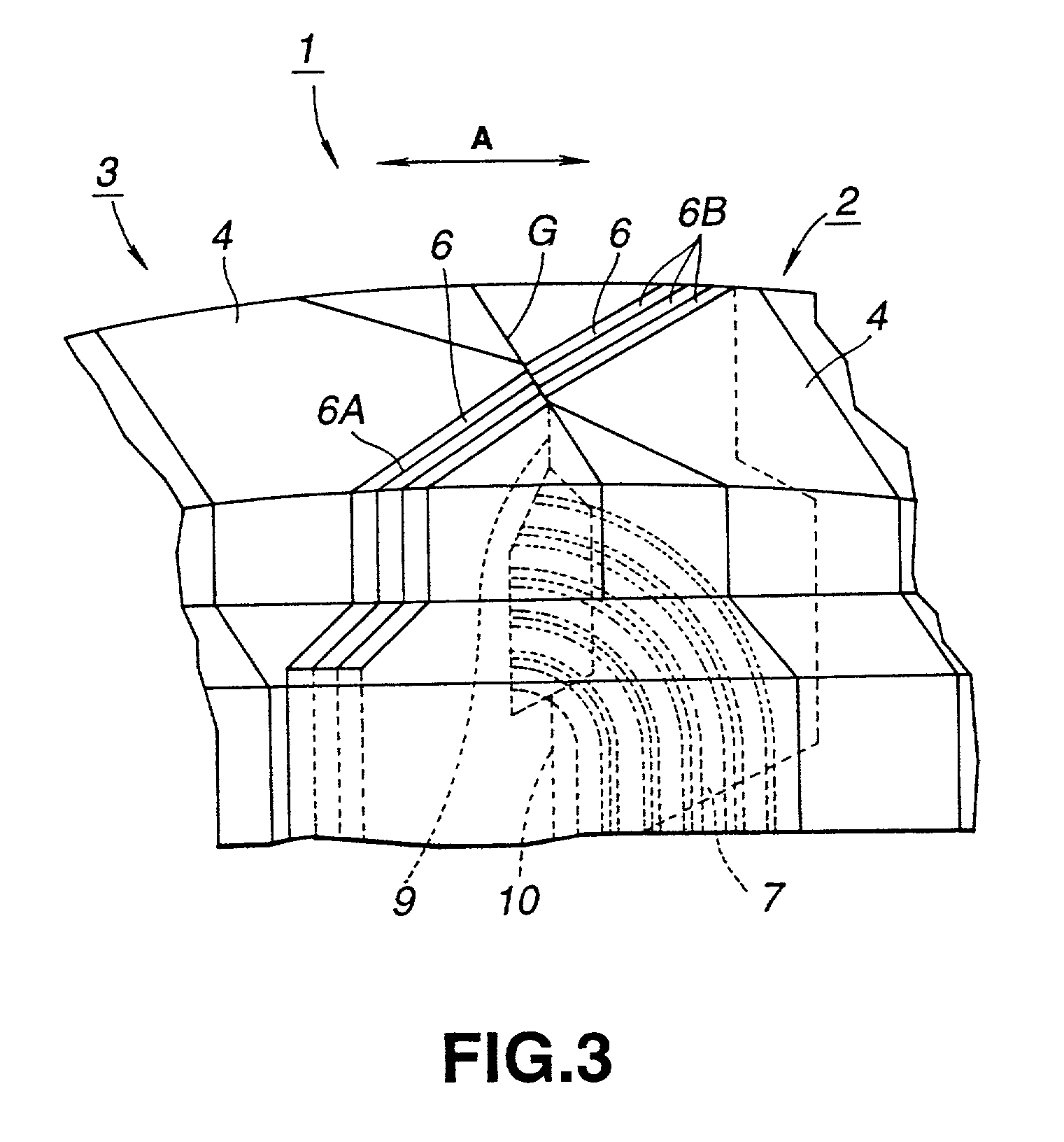
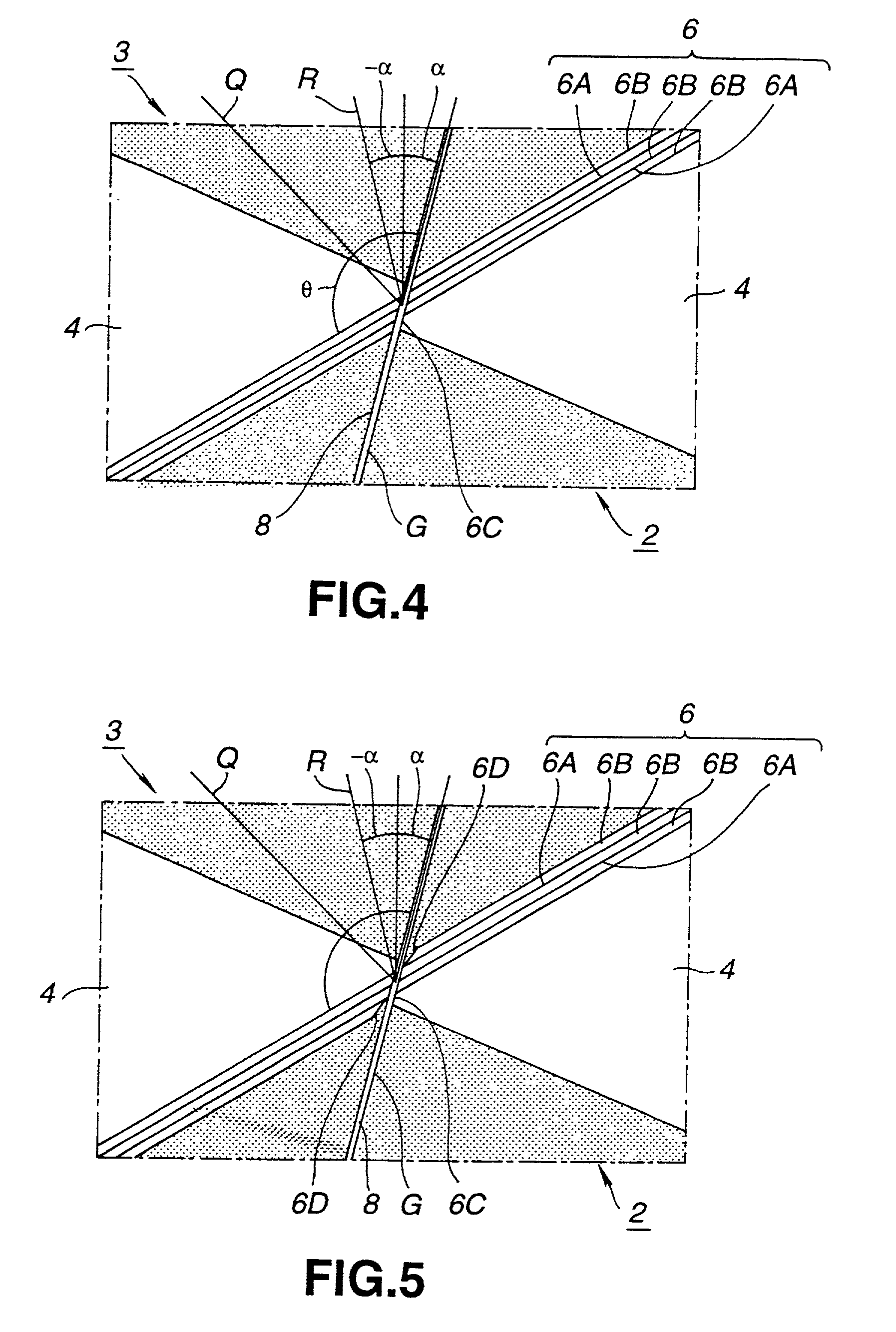
[0044] A magnetic head 1 according to the present invention is made up of a pair of magnetic head halves 2, 3 bonded together with a non-magnetic gap material G in-between, as shown in FIGS. 3 and 4. These magnetic head halves 2, 3 are each made up of a non-magnetic substrate 4 and a magnetic metal film 6 formed thereon. On at least one of the paired magnetic head halves 2, 3 is formed a coil 7 for magnetic excitation or detection of an induced voltage. In this magnetic head 1, the magnetic metal film 6 forms a magnetic core in such a state in which the paired magnetic head halves 2, 3 are bonded together with the gap material G in-between. On the magnetic head 1 is slid a magnetic recording medium in a direction shown by arrow A in FIG. 3, with the magnetic head halves 2, 3 being bonded together, thus reproducing the signal magnetic field recorde...


PUM

PropertyMeasurementUnit
track offset angleaaaaaaaaaa
thicknessaaaaaaaaaa
thicknessaaaaaaaaaa

Abstract

A magnetic head having optimum recording / reproducing characteristics and a method for producing the magnetic head. A pair of magnetic core halves 2, 3, each having a substrate 4 and a thin magnetic metal film 6 formed obliquely on it, are bonded together via a non-magnetic material C for defining a magnetic gap. A portion of the substrate faces a junction surface 8 of the magnetic core halves 2, 3. The substrate portion is arranged for facing an end face of the magnetic meta film 6 of the opposite side magnetic core half facing the junction surface 8.

Description

[0001] 1. Field of the Invention[0002] This invention relates to a magnetic head having a magnetic path formed by a magnetic metal film, and a manufacturing method therefor.[0003] 2. Description of Related Art[0004] In a magnetic recording / reproducing apparatus, such as a video tape recorder, researches in digitizing signals and recording the resulting digitized signals for improving the picture quality, are under way. In keeping pace therewith, researches in increasing the recording density and the recording frequency, are also progressing.[0005] Meanwhile, with the increased magnetic recording density and increased recording frequency, a magnetic head loaded on the magnetic recording / reproducing apparatus is required to have a high output and a low noise in the high frequency range. For example, in a compound metal-in-gap magnetic head used frequently as a magnetic head for VTR, in which a magnetic metal film is formed on a ferrite material and a coil is placed thereon, has a larg...

Claims


Application Information

Patent Timeline
Patent Type & Authority Applications(United States)
IPC IPC(8): G11B5/127G11B5/187G11B5/23G11B5/31G11B5/53
CPCG11B5/1276G11B5/1878G11B5/314Y10T29/49032Y10T29/49046Y10T29/49055Y10T29/49048G11B5/53
Inventor OGATA, SEIICHISAITO, TADASHIINAGUMA, TERUOTAKAHASHI, SHINJIINOUE, YOSHIHIKO
Owner OGATA SEIICHI
Why Eureka
Try Eureka