Smoking pipe

a technology of smoke pipe and pipe body, which is applied in the direction of tobacco pipes, applications, tobacco, etc., can solve the problems of high production cost, fragile and easily broken, and new smoking devices in which the smoke of the smoking material is drawn through water before inhalation

Inactive Publication Date: 2002-06-13
COUCH BRIAN
View PDF0 Cites 19 Cited by
  • Summary
  • Abstract
  • Description
  • Claims
  • Application Information

AI Technical Summary

Problems solved by technology

Smoking devices in which the smoke from the smoking material is drawn through water before inhaling are not new.
A common drawback of many of the prior art "water pipe" devices is that they are quite fragile and easily broken.
Another drawback is that they are usually of a rather complex construction making them expensive to produce.

Method used


Image

  • Smoking pipe
  • Smoking pipe
  • Smoking pipe

Examples


Embodiment Construction

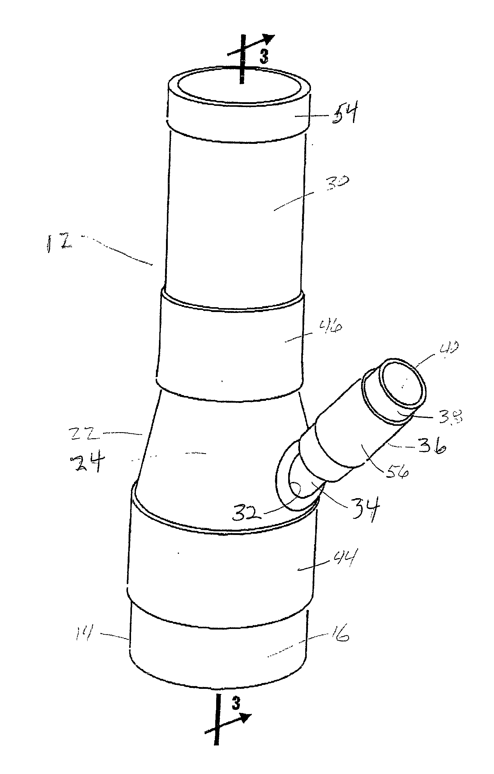
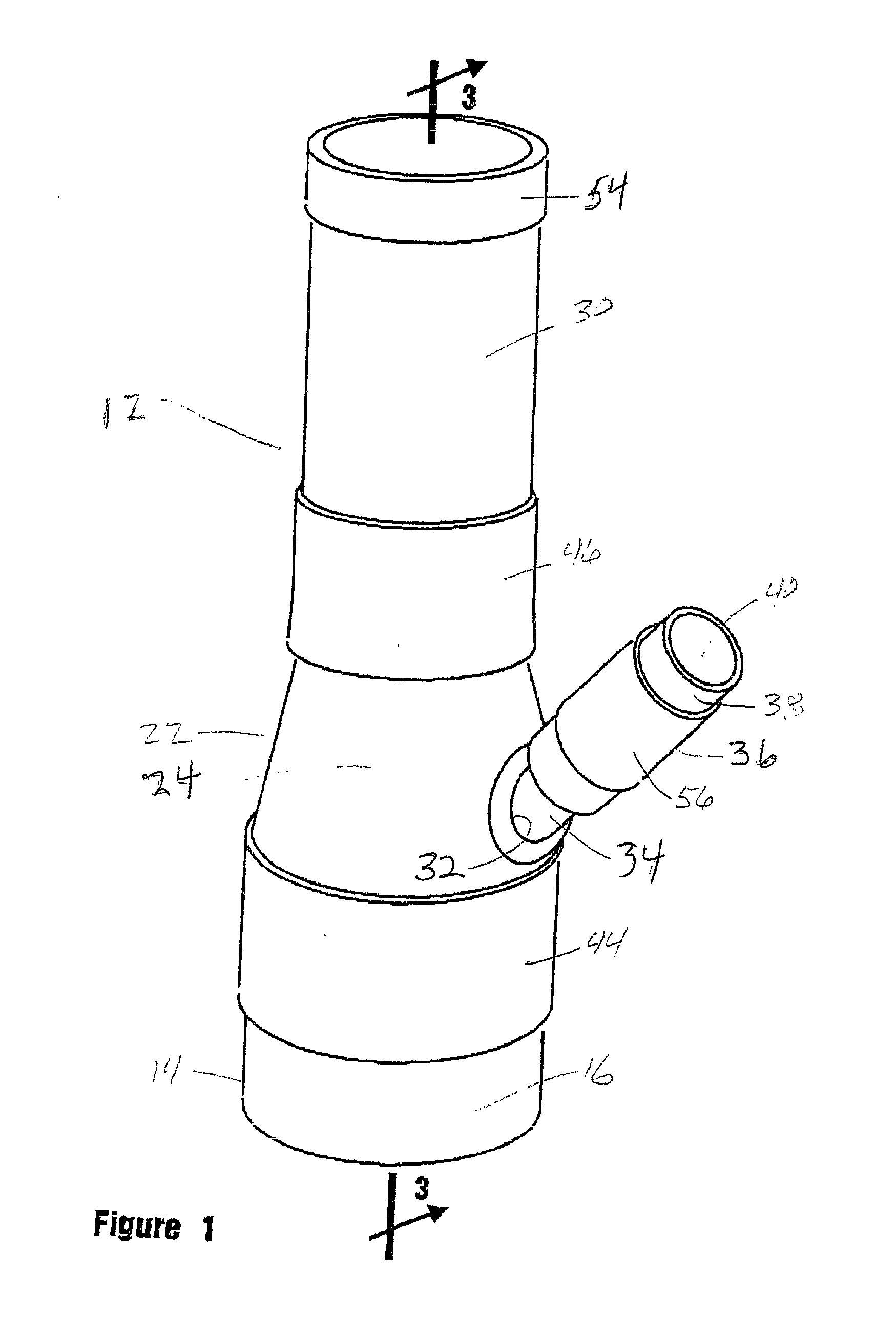
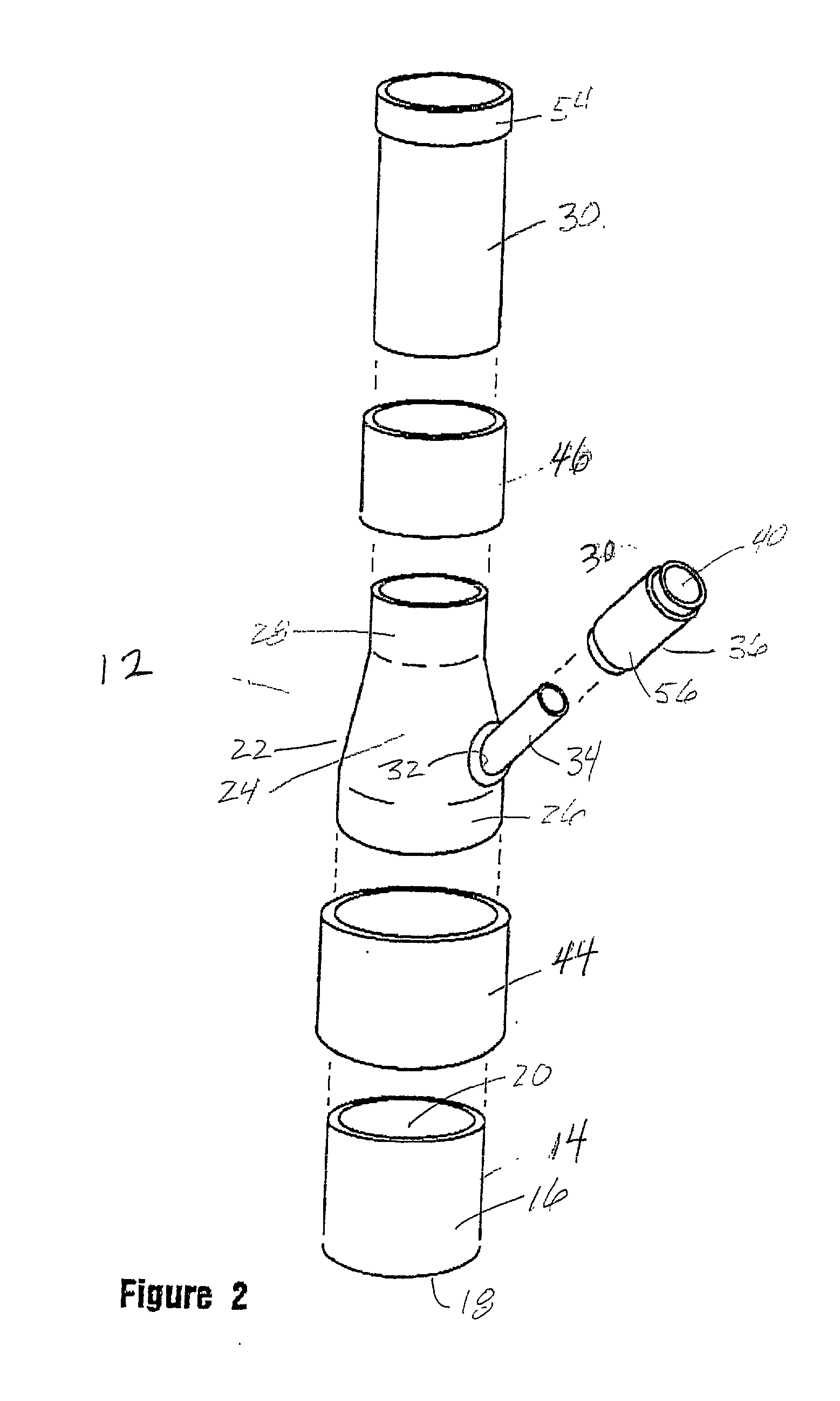
[0015] Referring to the drawings and particularly to FIGS. 1 and 2, one form of the smoking pipe of the present invention is there illustrated and generally designated by the numeral 12. As best seen by referring to FIG. 2, the smoking pipe here comprises a generally cup-shaped, stainless-steel, liquid-containing component 14 having a side wall 16 and a bottom wall that cooperate to define a liquid containing chamber 20. Slidably interconnected to liquid containing component 14 is a stainless steel connector segment 22 having a tapered side wall 24. Tapered side wall 24 interconnects and spans a first, generally cylindrically shaped skirt portion 26 that telescopically receives the generally cylindrically shaped wall 16 of the liquid containing component. Connected at the upper extremity of tapered side wall 24 is a second generally cylindrically shaped skirt portion 28 which is telescopically received within an upwardly extending, generally cylindrically shaped, stainless-steel mou...


PUM


Abstract

A smoking pipe of a stainless-steel, modular, slip-fit design having an external sealing system comprising a plurality of elastomeric sleeves which sealably interconnect the components of the modular design. The smoking pipe is compact, lightweight and can be readily dissembled for ease of transport and storage. Further, the smoking pipe is dishwasher safe, is easy to clean and can be safely sterilized by conventional means.

Description

[0001] 1. Field of the Invention[0002] The present invention relates generally to smoking devices. More particularly, the invention concerns a smoking pipe in which the smoke is drawn from a smoking material receiving bowl through water and then into a mouthpiece into the mouth of the user.[0003] 2. Discussion of the Prior Art[0004] Smoking devices in which the smoke from the smoking material is drawn through water before inhaling are not new. These types of smoking devices, which are sometimes called "water pipes", have been in use throughout the world for many years.[0005] A common type of prior art water pipe comprises a liquid-accumulating glass flask having a mouthpiece associated with the upper portion thereof. A pipette or tube typically extends into the flask to a point above the bottom thereof. Disposed at the top of the pipette is a smoke-receiving bowl. The glass flask is usually provided with an opening that sealably receives an apertured rubber stopper which accepts the...

Claims


Application Information

Patent Timeline
Patent Type & Authority Applications(United States)
IPC IPC(8): A24F1/30
CPCA24F1/30
Inventor COUCH, BRIAN
Owner COUCH BRIAN
Why Eureka
Try Eureka