Interbore cooling system

US20020100435A1Inactive Publication Date: 2002-08-01GASOLINEIAM NASIONAL BERHAD
0 Cites 15 Cited by

Patent Information

Authority / Receiving Office
US · United States
Current Assignee / Owner
Publication Date
2002-08-01
Estimated Expiration
Not applicable · inactive patent

Smart Images

  • Figure 1
    Figure 1
  • Figure 2
    Figure 2
Patent Text Reader

Abstract

A cooling system for cooling an interbore bridge of a cylinder block of a water cooled engine, the interbore bridge having a top surface and a central region of minimum width; the cylinder block having a water jacket; the cooling system including at lest one water passage extending from the top of the interbore bridge adjacent the central region to the water jacket. A method of forming the cooling system, and a cylinder block so formed, are also disclosed.
Need to check novelty before this filing date? Find Prior Art

Description

CROSS-REFERENCE TO RELATED APPLICATION

[0001] This application is based upon and claims priority to Malaysian Patent Application No. PI 2000 6079, filed Dec. 21, 2000, which application is hereby expressly incorporated by reference.FIELD OF THE INVENTION

[0002] This invention relates to improvements in cooling systems of a water-cooled engine and preferably, though not exclusively, to a cooling system to cool the upper regions of an interbore bridge of such an engine.BACKGROUND OF THE INVENTION

[0003] The narrow structure between two cylinders of a cylinder block is known as the interbore bridge. It has a high thermal concentration. This region has high surface to volume ratio, and easily be overheated if exposed to high heat sources. Heat sources can come from combustion within the cylinders, and also from the friction between the piston assembly and cylinder wall.

[0004] Problems are likely to occur once the surface temperature of the cylinder wall at the interbore bridge reaches 180....

Examples

Embodiment Construction

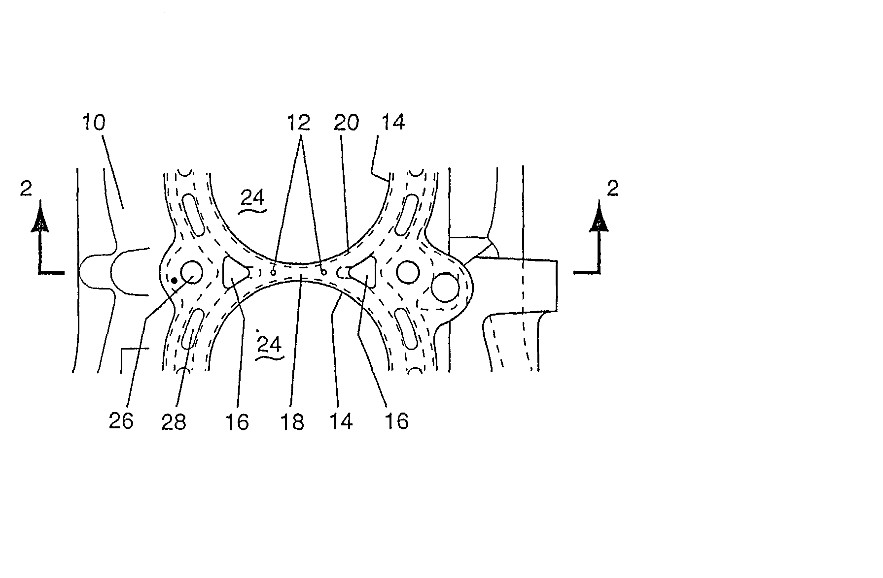
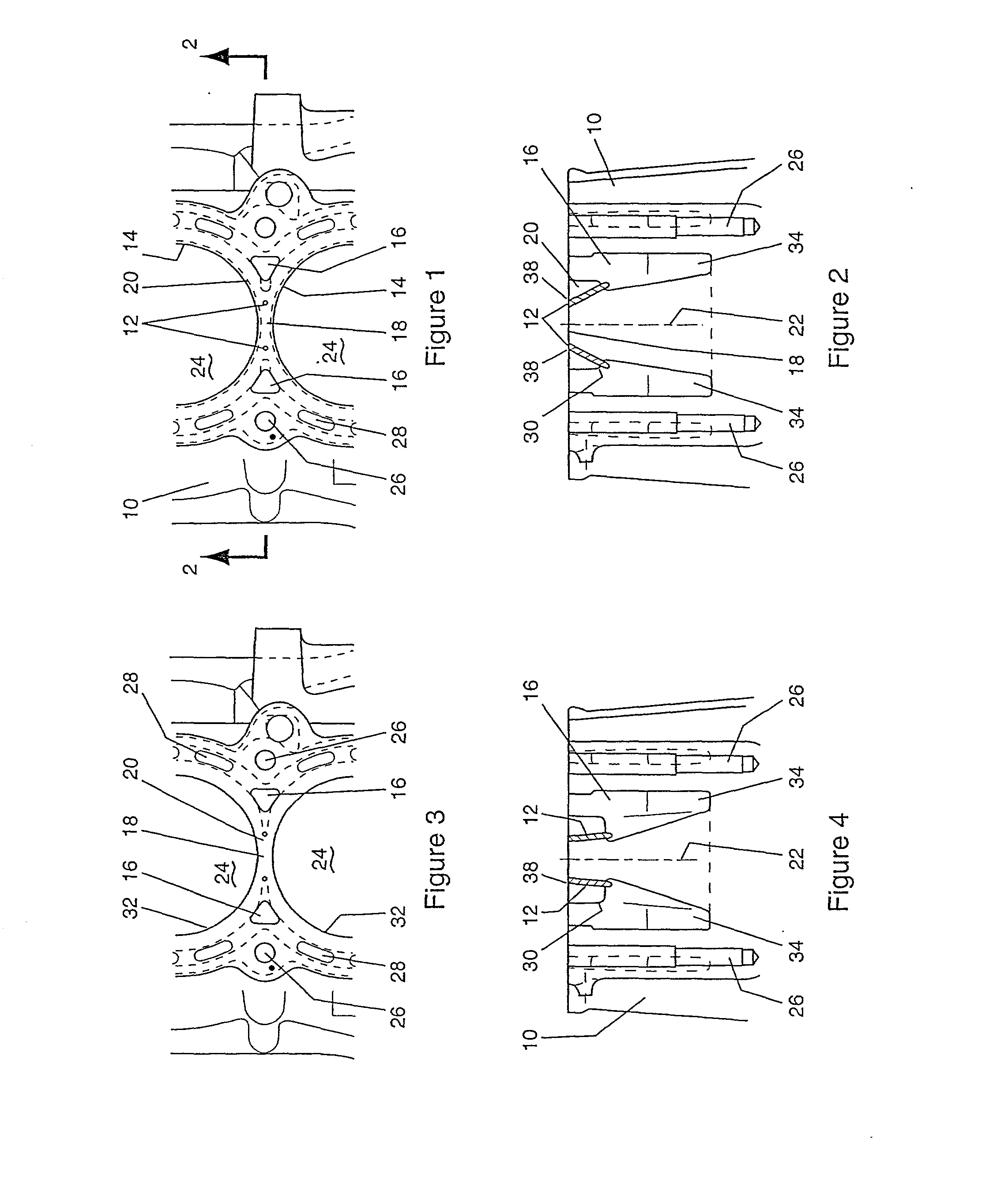
[0038] FIG. 1 and 2 show angled drilled passages 12 in cylinder block 10, the passages 12 not crossing each other. The block 10 has a number of bores 24 each having 2 mm liner 14. After the drilled passages 12 are made, there is still 2.5 mm of metal and 2 mm of liner remaining. Together with a 4 mm minimum gasket width, the gap will provide for adequate sealing. Head bolt holes 26 and water jacket openings 28 are provided, as is normal.

[0039] In order to provide at least 4 mm of metal between a water jacket 16 and each liner 14, the closest the water jacket 16 can get to the vertical axis 22 of the centre 18 of the interbore bridge 20 is about 12 mm. As can be seen, the top 38 of the passages is adjacent the centre 18--the region of highest heat concentration. However, they may be at or in the central region 18.

[0040] In FIG. 2, the water jacket 16 is extended to provide a surface 30 normal to water passages 12. The surface 30 is relatively flat and is required to ensure the dill b...